Torsion-Optimized High-Clearance Hitch
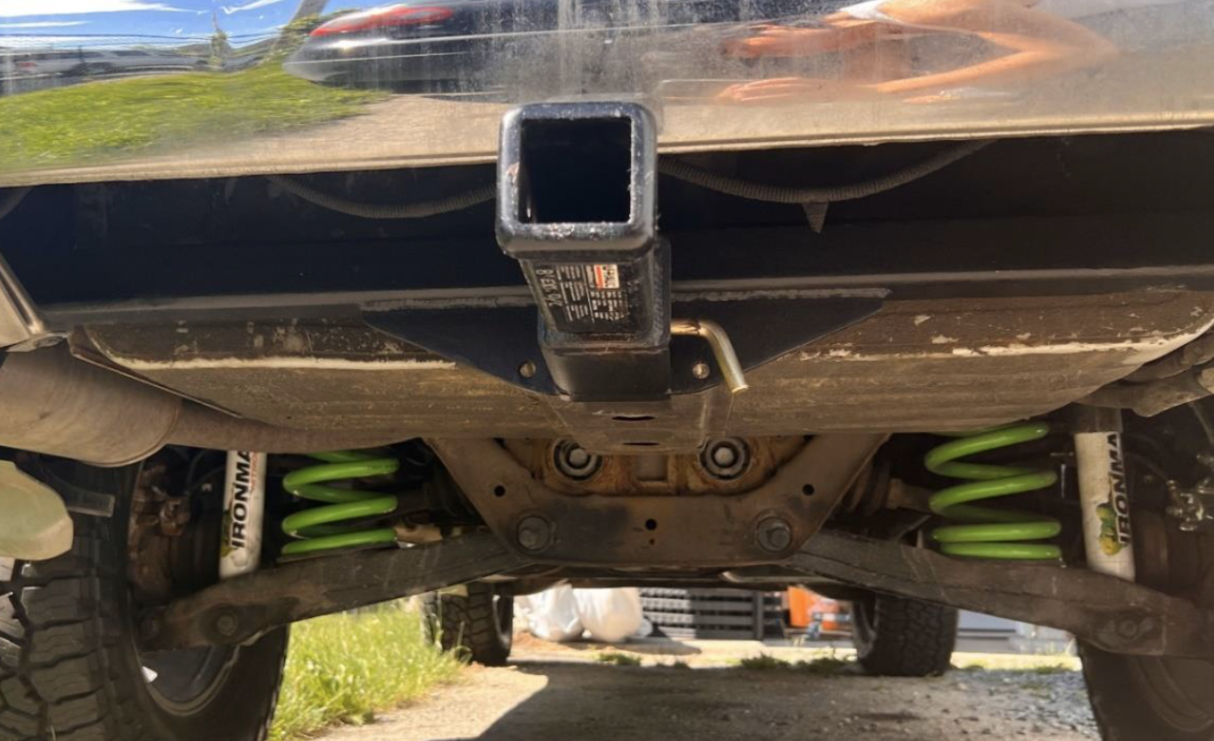
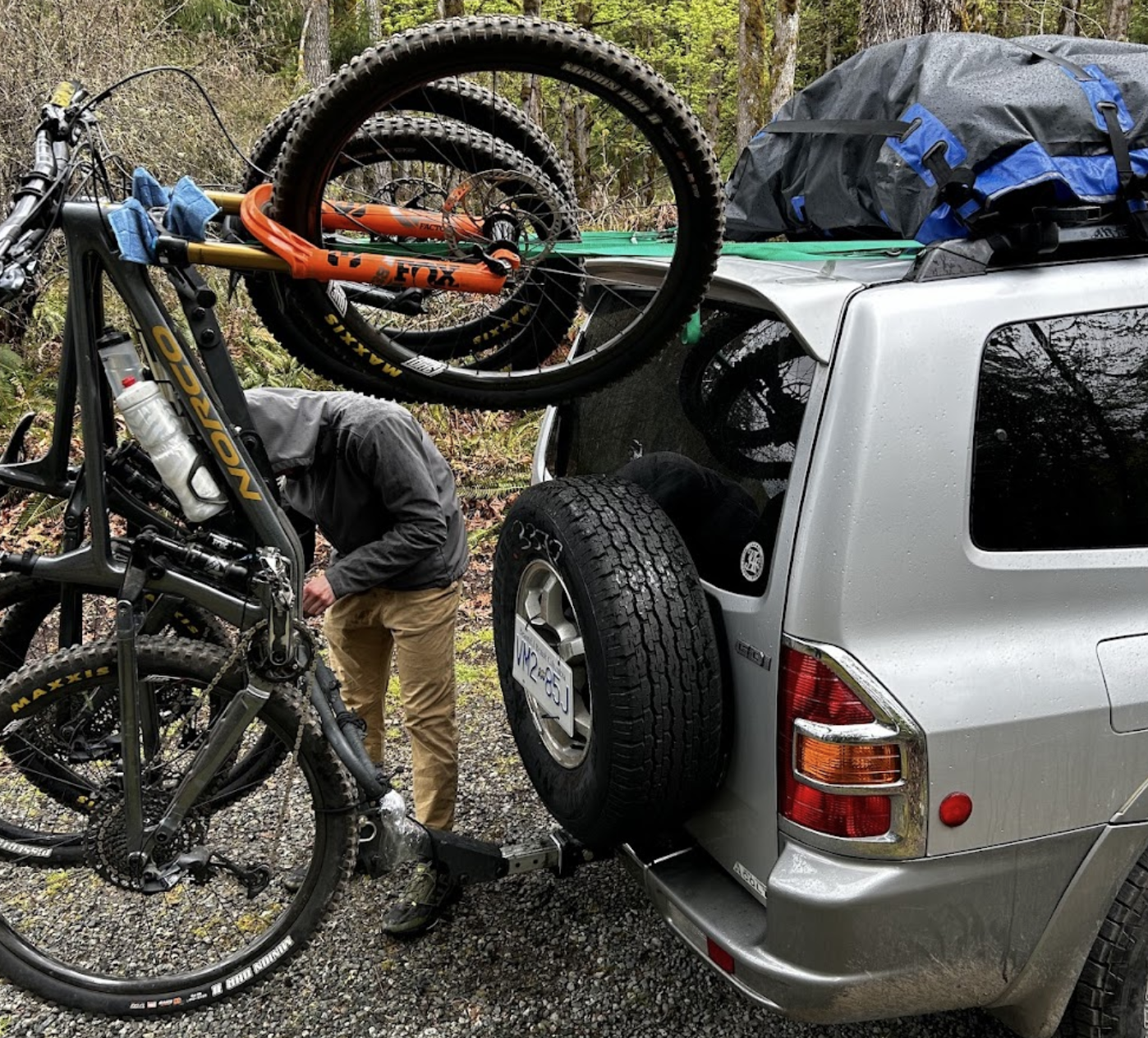
Two summers ago, I scavenged materials to build a last-minute trailer hitch for a mountain biking trip. Although it was functional and lasted, whenever we hit a large bump, the bike rack would swing backwards.
To figure out what was wrong, I wrote a MATLAB script then did a more accurate final check with FEA.
The goal: minimize the swinging of the bike rack using a first principles analysis without over-complicating the design, and ensuring it won't snap going over a cross ditch.
Project summary (TLDR) in the box below:
Design Goal: Redesign a trailer hitch to minimize angular deflection while maintaining a Factor of Safety of 2.0 under dynamic loading (4G bump scenario).
The Problem: Two summers ago I built a hitch on a tight budget, and timeline, for a mountain biking trip. It worked, but whenever we hit a large bump the bike rack would swing backwards. I wanted to understand the root cause and fix it properly.
The Approach: I started with first principles to isolate which component was causing the deflection. Using the "softest spring" principle, I identified the crossbar as the primary issue, torsional twist accounted for 94% of the vertical deflection at the tip. I built a parametric MATLAB script using Bredt's Thin-Wall Formula to model the system (receiver as cantilever beam, crossbar as a non-circular shaft in torsion), then validated the final design with FEA and MATLAB.
For the geometric optimization, I analyzed the governing equation for angle of twist and found that the midline area has a squared relationship with stiffness while wall thickness is linear. Upsizing from 2.0" to 2.5" gave a 52.6% theoretical stiffness gain without needing custom sizes or complicated fabrication. When I checked the weld stresses using Norton's "weld as a line" method, the receiver-to-crossbar weld showed a 0.95 FoS under 4G loading, theoretical failure. A weighted matrix showed adding an angle iron gusset would be the ideal design decision.
The Result: The V2 design reduced tip deflection by 31% and maintained an average 2.7 FoS at critical nodes under the 4G loading scenario. MATLAB predictions matched FEA within 8.9% for V1, confirming the validity of the setup. The V2 geometry showed a larger 37% variance due to local wall distortion (b/t ratio increased from 8 to 10), which highlighted where Bredt's Formula breaks down and FEA becomes necessary.
What I learned: This project reinforced the "fail fast, learn fast" value for me. The V1 gave me real-world feedback and a baseline to improve from, proving that iterative design beats analysis paralysis.
End of summary.
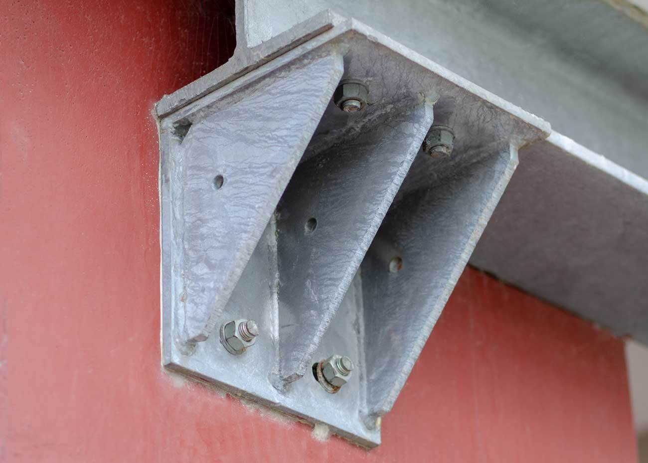
Part 1: The "Scrappy" Prototype
The project began with a $50 budget and a tight timeline. Market options cost nearly 10 times that and significantly reduced departure angle. So I set out to fix that.
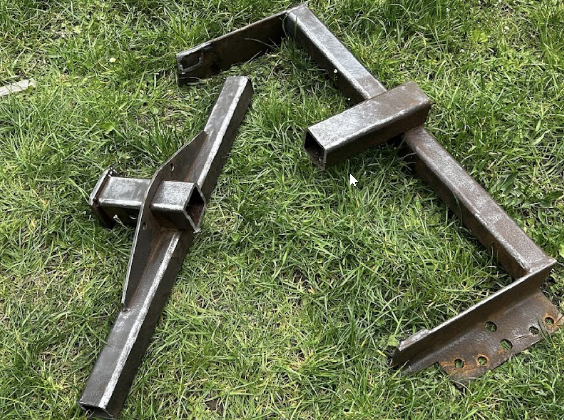
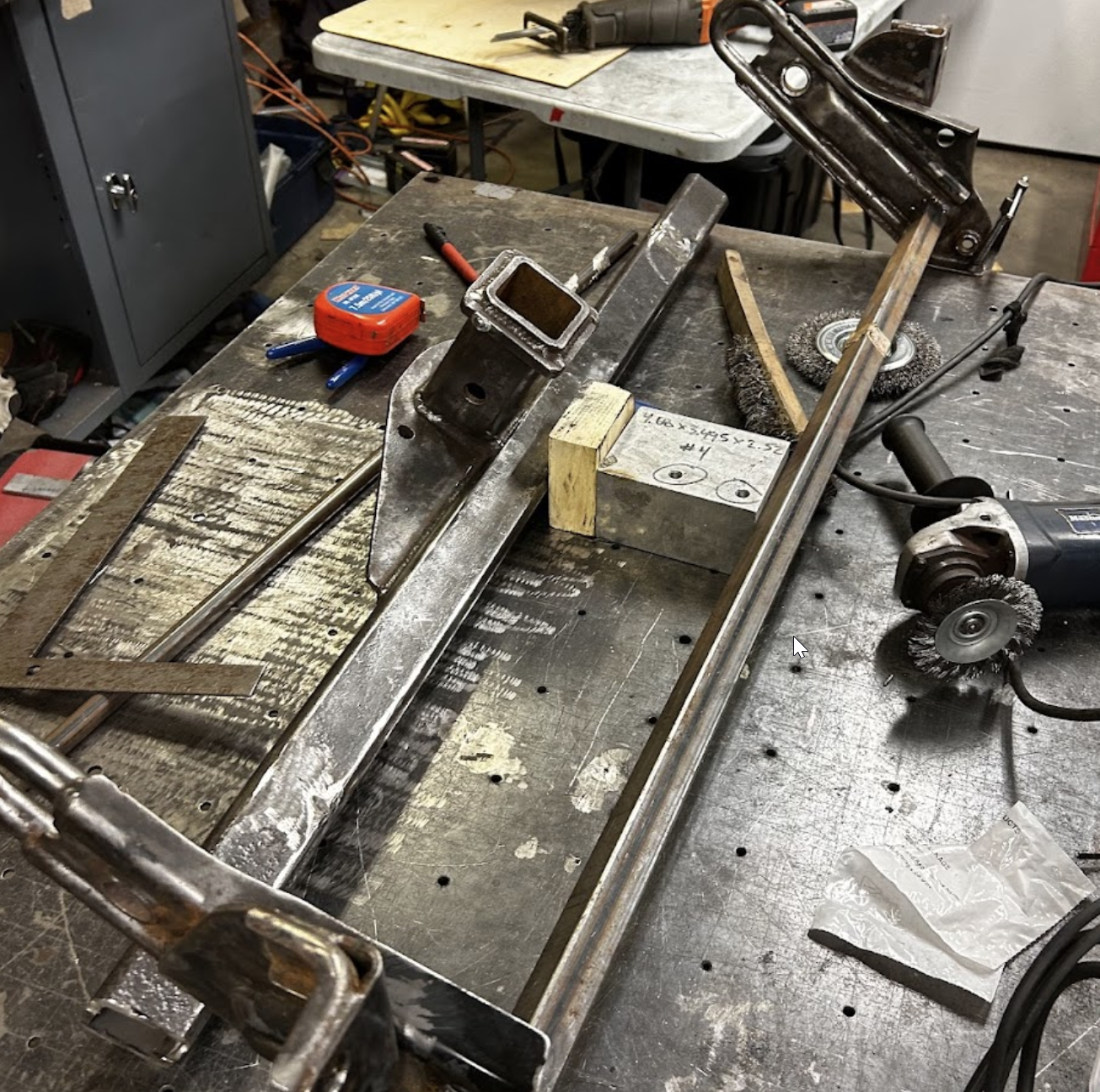
- Fabrication Strategy: I salvaged a free donor hitch from marketplace, repurposing it to fit with the tow bar that came with the vehicle
- The Field Test: During our 4-day trip the hitch experienced significant angular deflection during rougher terrain.
Part 2: The Analysis
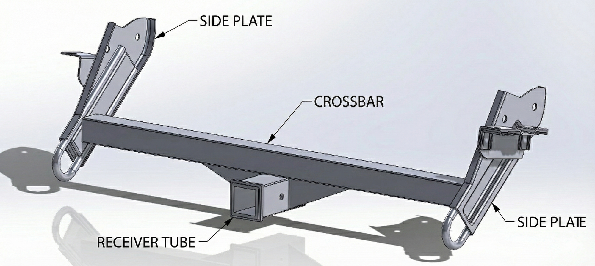
For the initial mathematical model , I had to determine which components contributed the most to deflection. I chose to isolate the receiver & crossbar assembly, treating the side plates as rigid fixed supports for the initial analysis.
The Justification:
- Higher Relative Stiffness: The side plates are vertically oriented with a high Area Moment of Inertia (I) relative to the load
- Dual Load Distribution: There are two side plates sharing the load.

- The "Softest Spring" Principle: In a series mechanical system, deflection is driven by the most compliant component.
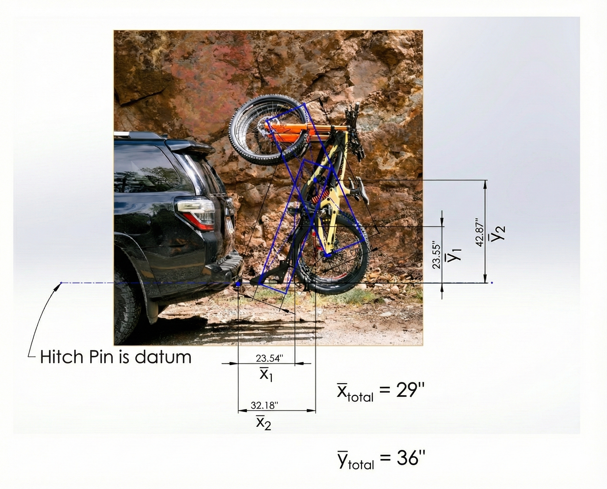
Lacking CAD files for the bike rack, I simply used a scaled image and approximated mass distributions to find the systems COG.
First Principles Modeling (MATLAB)
I wrote a MATLAB script to act as a simple parametric model that gives quick feedback on changes. Creating a simple mathematical model also provides better intuition for variables and their sensitivities. I modeled the receiver tube as a cantilever beam, and the crossbar as a non-circular shaft in torsion.
Assumptions & Simplifications:
- Crossbar beam bending due to normal force was deemed non-relevant
- Would not significantly impact real world bike rack movement as most deflection is due to the system's angular deflection.
- Bredt's thin wall approximation was used to find crossbar angle of twist.
--------------------------------------------------
 [3] STATIC DEFLECTION RESULTS
 Tip Angle (Twist+Bend)         :     0.21 deg
 Vertical Drop (Receiver)       :   0.0174 in
      > Due to Bend    :   0.0010 in
      > Due to Twist   :   0.0164 in
 Vertical Drop (Bike COG)       :   0.1121 in
==================================================
MATLAB Output (180lb Load, 2.0x2.0x0.25" crossbar)
This analysis confirmed angular deflection of the hitch assembly, represented as vertical drop of the tip, was primarily caused by torsion (94%).
Part 3: The Solution
To find the most efficient way to increase crossbar stiffness, I analyzed the governing equation for angle of twist.

- Torque (T), Length (L), and Material (G) were all constrained
- The Polar Moment of Inertia (J) was the only parameter I could realistically influence.

Using Bredt’s Formula for polar moment of inertia, I compared the variables:
- Wall Thickness (t): Has a linear relationship with stiffness
- Midline Area (Am): Has a squared relationship.
| Section Profile (in) |
Torsional Constant J (in4) |
Area (in2) |
Efficiency Ratio (J/Area) |
|---|---|---|---|
| Solid Square (2x2) | 2.25 | 4.00 | 0.56 |
| Solid Circle (2⌀) | 1.57 | 3.14 | 0.50 |
| Hollow Square (2x2x0.25) | 1.34 | 1.75 | 0.77 |
| Hollow Circle (2⌀x0.25) | 1.07 | 1.37 | 0.78 |
Different shapes have a different balance of area and perimeter:
- Squares and circles are the most efficient shapes for torsion
- Hollow sections increase torsional efficiency because shear stresses concentrate near the outer surface
- Circular tubes add fabrication complexity with minimal performance gain.
Thus the hollow square shape is chosen.
| Crossbar Option | Deflection % Improvement (Wt: 5) |
Cost % (Wt: 3) |
Integration & Packaging (Wt: 3) |
Weighted Score |
|---|---|---|---|---|
| A. 2.5" x 0.250" Wall | 3.5 (52.6%) | 5 | 5 | 47.5 |
| B. 2.5" x 0.313" Wall | 4 (60.4%) | 3.5 | 5 | 46.5 |
| C. 3.0" x 0.25" Wall | 4.5 (65.9%) | 4 | 3.5 | 45.0 |
| D. 3.0" x 0.375" Wall | 5 (76.9%) | 3 | 3.5 | 44.5 |
In this weighted matrix, option A was selected as the best option for the requirements. It had a significant deflection reduction while having the best cost and ease of integration. The other options lacked availability, fitment, or space constraints.
Part 3a: The Location of Interest
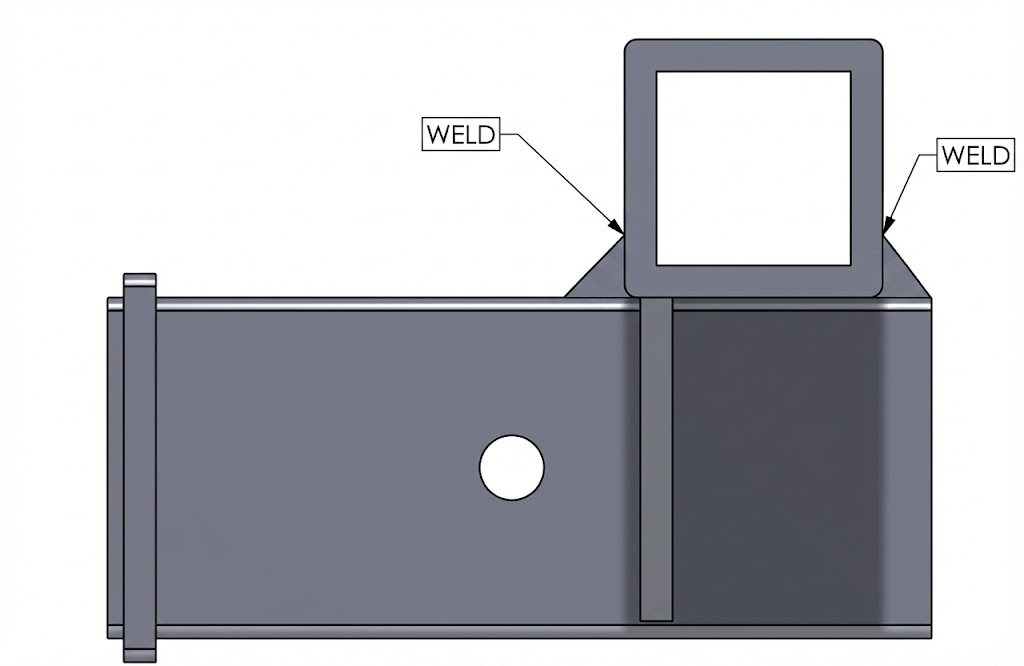
The likely failure point (the weld in tension), was checked using the line-weld method in Norton's Machine Design:

This equation finds the total force per unit length on the weld from direct shear (V), and the torque (T), without any complex derivations.
The weld's throat stress was obtained with this relationship:

- Material Specs: Assumed a standard E70 Electrode (Tensile Strength = 70,000 psi)
- Acceptance Criteria: Per AWS D1.1, the allowable shear stress was limited to 30% of the electrode's tensile strength (~21,000 psi).
==================================================
 DYNAMIC ANALYSIS (4.0 G Pothole Load)
--------------------------------------------------
 Dynamic Load                   :   720.00 lbs

 COMPONENT            | F.O.S.       | STATUS
--------------------------------------------------
 Weld Shear           |         0.95 | >> FAIL <<
 Crossbar Torsion     |         1.83 | PASS
--------------------------------------------------
 Dynamic Tip Drop               :   0.0695 in
      > Due to Bend    :   0.0040 in
      > Due to Twist   :   0.0655 in
 Dynamic COG Drop               :   0.4484 in
==================================================
MATLAB Output (180lb Load, 2.0x2.0x0.25" crossbar)
This analysis revealed a safety factor of 0.95 in a 4G dynamic event, meaning theoretical failure of the weld.
| Design Option | Stress Reduction (Wt: 5) |
Manufacturability (Wt: 4) |
Cost / Avail (Wt: 3) |
Weighted Score |
|---|---|---|---|---|
| Angle Iron Gusset | 3 | 5 | 5 | 50 |
| Triangle Gusset | 4 | 3 | 4 | 44 |
| Full Box Plating | 5 | 2 | 3 | 43 |
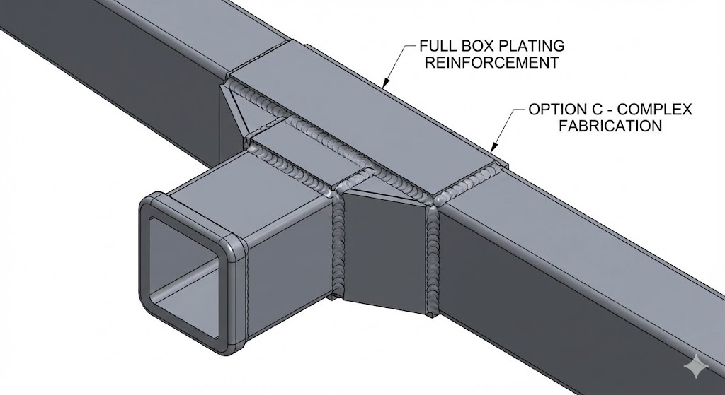
Triangle gusset (left) and Full box plating (right)
Reinforcement was required to avoid failure of the critical weld. Used a weighted matrix, I selected an angle iron gusset due to the simplicity and minimal additional cost.
Part 4: FEA vs. MATLAB Comparison
To verify the designs in more depth, I ran FEA simulations with the following setup:
- Simplified boundary conditions by fixing each end of the crossbar for direct comparison to MATLAB results
- Applied remote load using previously derived COG location
- Used standard curvature-based mesh (decreased element size around corners/features.
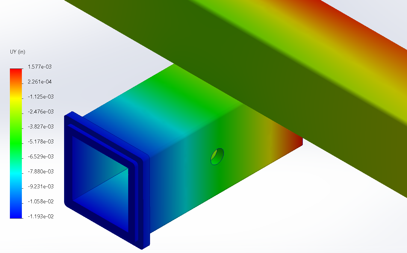
| Validation Metric (V1) | Load Case | MATLAB Prediction (in) |
FEA Result (in) |
Variance |
|---|---|---|---|---|
| Vertical Deflection | 180 lbs | 0.0174 | 0.0189 | 8.9% |
Comparing MATLAB results to FEA I found an 8.9% variance in the V1 results which is a great result that reinforces that the model was accurate.
==================================================
STATIC ANALYSIS SUMMARY
--------------------------------------------------
Static Load Applied            :   180.00 lbs

COMPONENT            | F.O.S.       | STATUS
--------------------------------------------------
Weld Shear           |         3.81 | PASS
Crossbar Torsion     |         7.32 | PASS
--------------------------------------------------
[3] STATIC DEFLECTION RESULTS
Tip Angle (Twist+Bend)         :     0.21 deg
Vertical Drop (Receiver)       :   0.0174 in
     > Due to Bend    :   0.0010 in
     > Due to Twist   :   0.0164 in
Vertical Drop (Bike COG)       :   0.1121 in
==================================================
MATLAB Output (180lb Load, 2.0x2.0x0.25" crossbar)
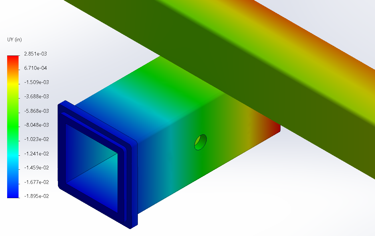
| Validation Metric (V2) | Load Case | MATLAB Prediction (in) |
FEA Result (in) |
Variance |
|---|---|---|---|---|
| Vertical Deflection | 180 lbs | 0.0087 | 0.01193 | 37% |
When the test was repeated with the V2 geometry there was a significant 37% variance.
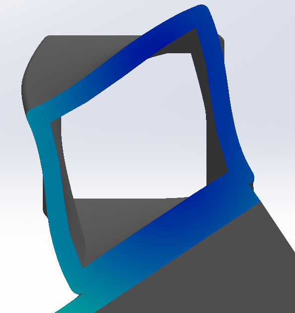
The variance in results can be attributed to more prominent local wall deformation in the V2 geometry due to an increased width to thickness ratio of 10 (V2) from 8 (V1). This is since Bredt's Formula assumes a rigid cross-section that does not deform in order to simplify calculations.
==================================================
STATIC ANALYSIS SUMMARY
--------------------------------------------------
Static Load Applied            :   180.00 lbs

COMPONENT            | F.O.S.       | STATUS
--------------------------------------------------
Weld Shear           |         3.85 | PASS
Crossbar Torsion     |        12.10 | PASS
--------------------------------------------------
[3] STATIC DEFLECTION RESULTS
Tip Angle (Twist+Bend)         :     0.11 deg
Vertical Drop (Receiver)       :   0.0087 in
     > Due to Bend    :   0.0010 in
     > Due to Twist   :   0.0077 in
Vertical Drop (Bike COG)       :   0.0586 in
==================================================
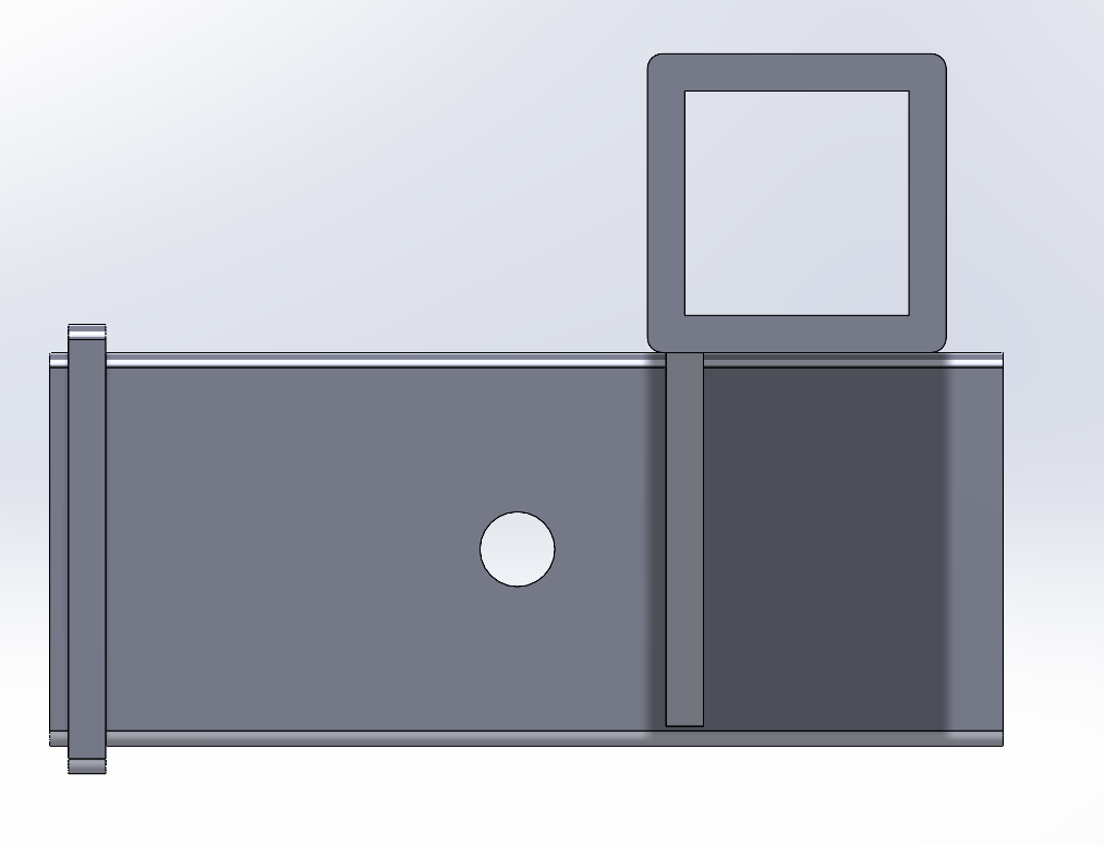
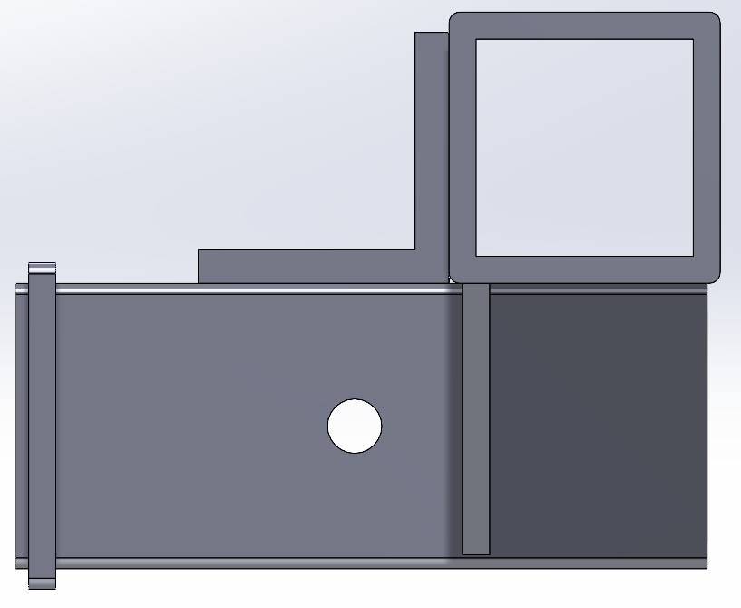
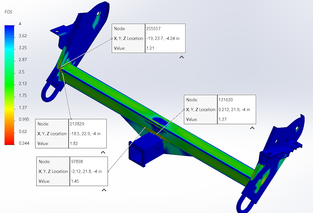
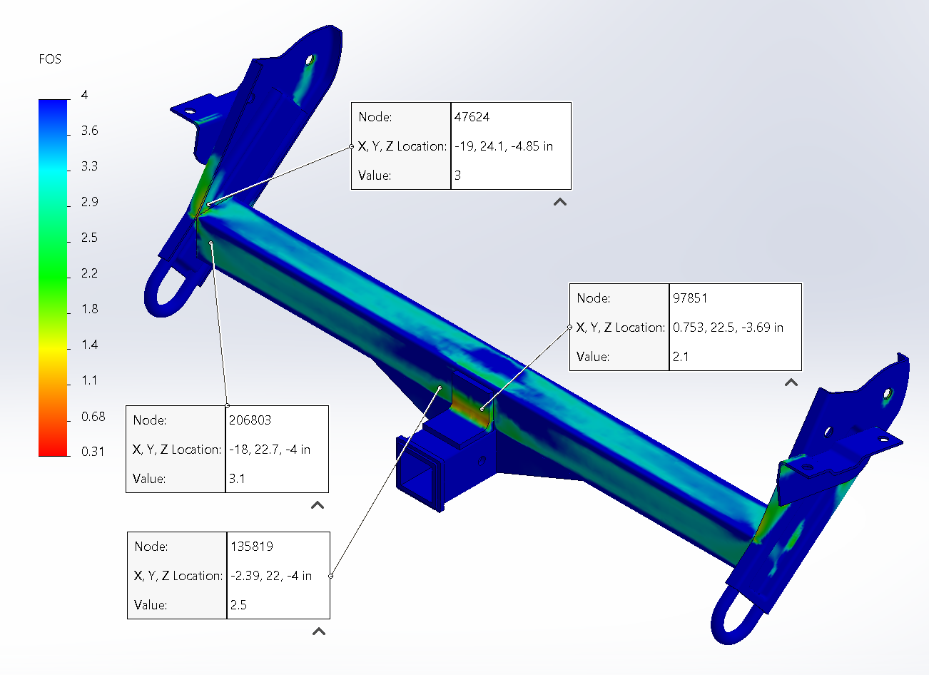
Part 5: V2 Practical Safety Validation
To validate the V2 design for real-world durability, I applied a "Worst Case" dynamic load to the full assembly, including side plates, ribs, and gusset.
| Simulation Parameter | Value | Notes |
|---|---|---|
| Design Requirement | Safety Factor > 2.0 | Yield |
| Load Condition | 4G Dynamic Event | Severe pothole/impact event |
| Applied Load | 720 lbs | 4G static equivalent |
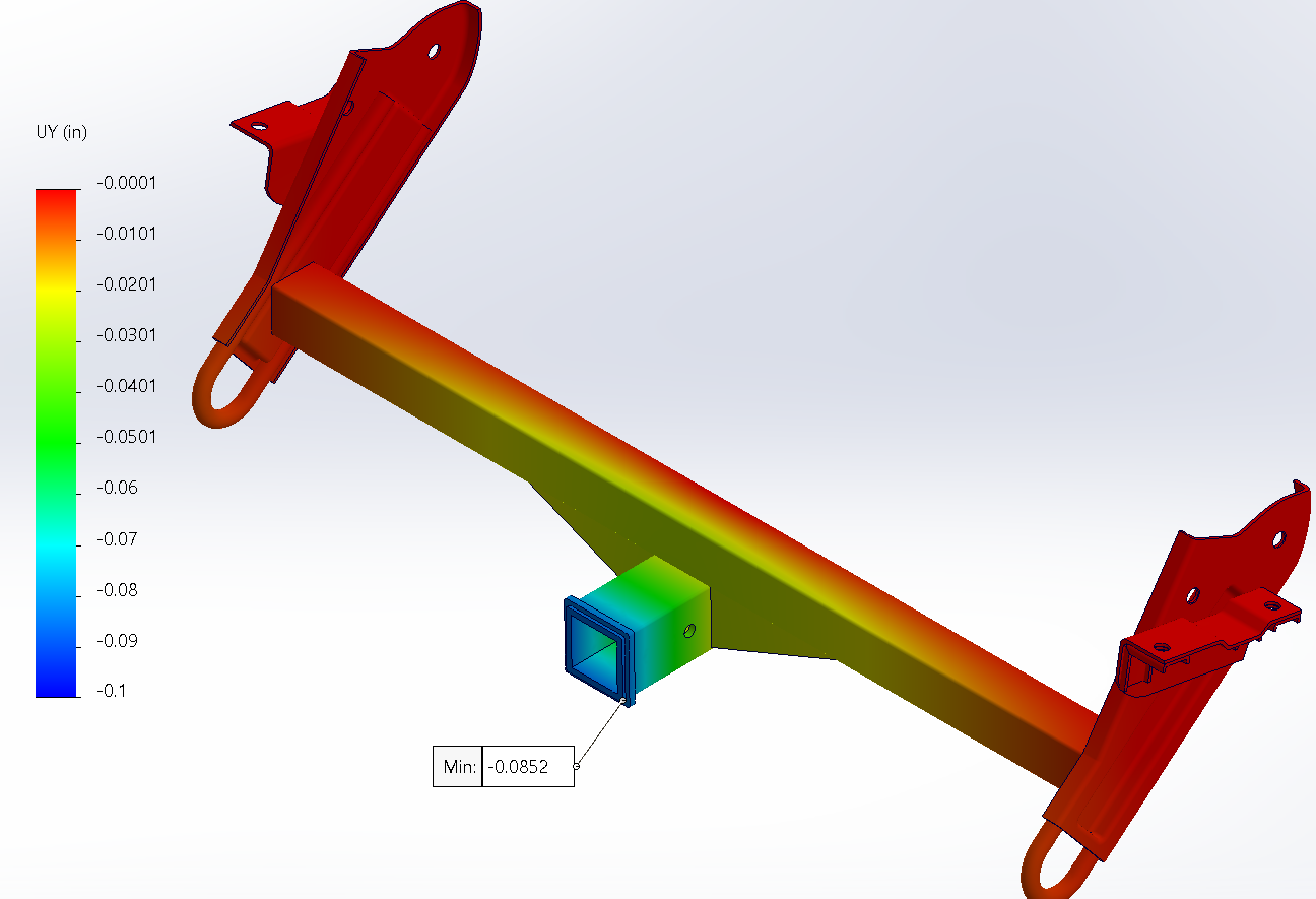
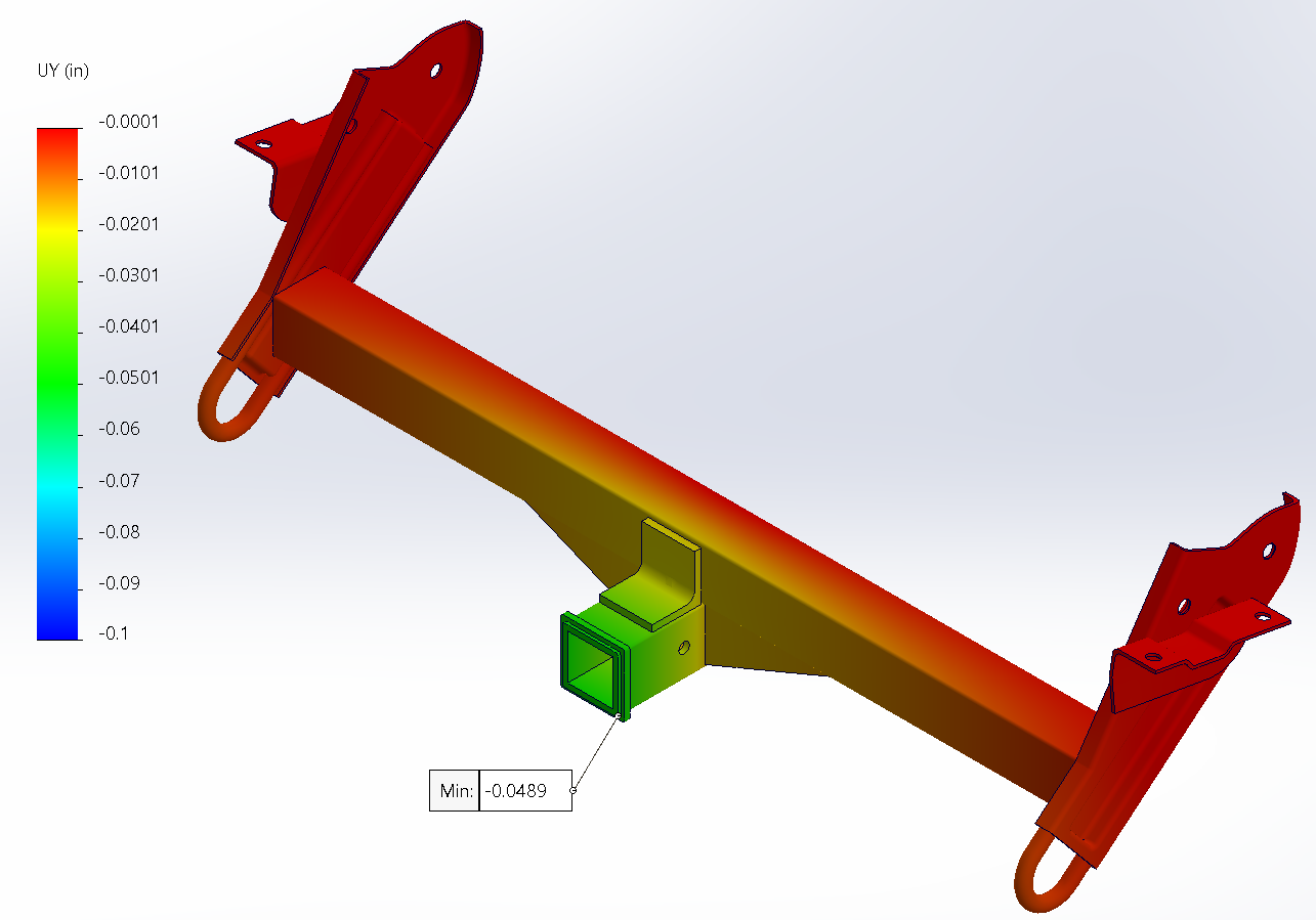
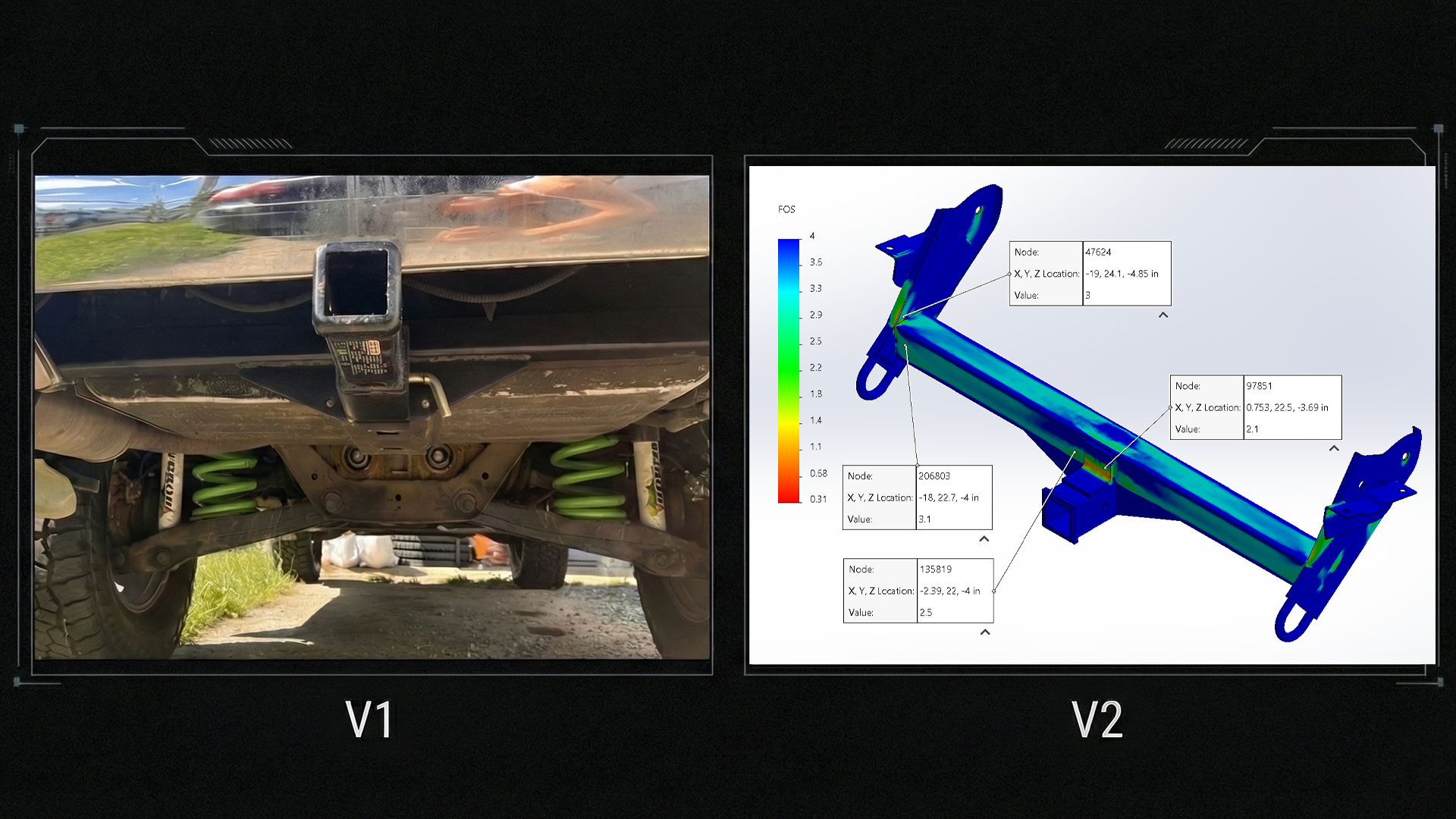
V1 (left) and V2 (right)
| Performance Metric | Result | Interpretation |
|---|---|---|
| Global Safety | AVG Node Safety Factor ≈ 2.7 | Exceeds 2.0 target |
| V2 Stiffness Gain | +46% Stiffness | (31% deflection reduction) |
| Assumption Validation | Side plate deflection ≈ 8% of total | Supports earlier simplification |
FEA Interpretation & Stress Analysis:
- Simulation Artifacts were observed where the crossbar joins the side plates. The side plates are not perfectly flat, as they are repurposed. Normally the gaps would be filled with weld but they weren't included in the simulation
- A Stress Concentration was observed at the corner of the angle iron gusset. Under the extreme 4G load case this area experiences local yielding which would relieve some stress concentrations in practice (ductile material).
The gusset stress concentration is not a significant concern as this scenario demonstrates a catastrophic event, not a cyclical load. This would become an issue if pushed past the design requirements (see below).
Part 6: Future Optimization (V3 Concept)
The V2 design met all safety goals, significantly increased stiffness, and remained in scope/practical. For a more heavy-duty application, I would recommend the following improvements:
1. Crossbar Reinforcement ("Fish plating")
- Weld additional steel plates to the top and rear faces of the crossbar
- Increases local wall thickness, increasing torsional stiffness and decreasing local wall deformation.
2. Triangular Web Gusset
- Reinforce or replace angle-iron gusset with triangle gusset (triangle plates)
- This change would significantly reduce stress concentrations at the corner.
Part 7: Conclusion
This project taught me two things:
- First-Principles Thinking: Starting with hand calcs helped me reinforce my intuition on variables and their sensitivities. Upsizing the crossbar from 2.0” to 2.5” and getting a 46% stiffness increase, showed how a minor geometric change can yield major results.
- Bias for Action: The V1 prototype gave me a real world starting place and allowed me to iterate faster than trying to guess every way the design could fail. It also ended up teaching me better design intuition that I will carry over to future projects.
The V2 design met the design requirements and maintained its focus on an easy to fabricate design. For a ground up redesign I would have used more efficient geometry and simpler mounting plates, but the V3 concept notes serve as a good intermediate.