Overview
This started as a hackathon day in January 2026 with Russell Bilinski. We'd been looking at Caden Kraft's actuator work and wanted to build a backdrivable actuator ourselves, mostly to learn how the gearbox side works. Russell had a D6374 motor, an ODrive controller, bearings, and an encoder, so we started from there.
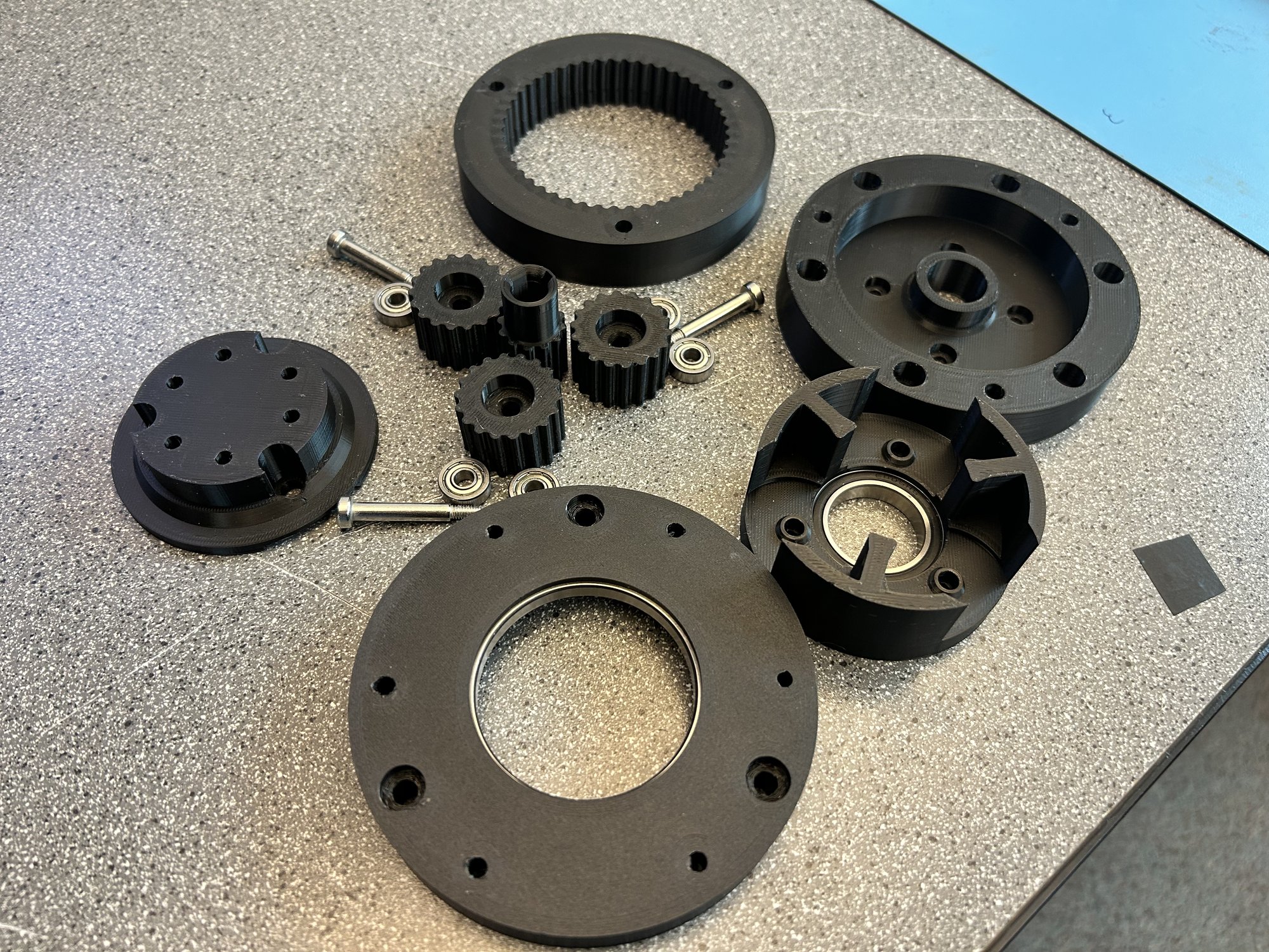
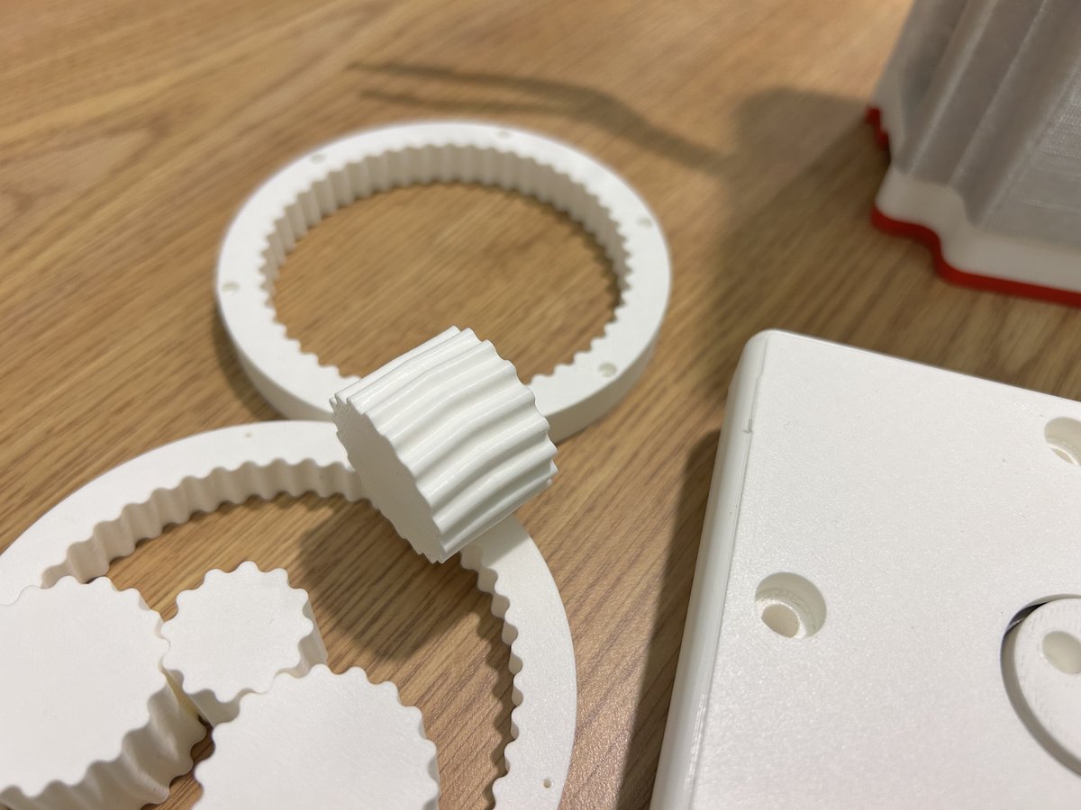
What I designed is the gearbox, a 5:1 planetary reduction between the motor and the output shaft, 3D-printed on a Bambu P1S. The design targets are the interesting part: low ratio, low backlash, low friction, and a backdrivable output. A low ratio multiplies torque without the reflected inertia of a high-ratio gearbox, so the output stays backdrivable and force and impedance control stay practical. Actuators built around a low-ratio reduction like this are called quasi-direct-drive.
Requirements
We set the initial requirements around backlash, backdrivability, torque, cost, and basic practicality for a student-built prototype.
| Requirement | Target | Type |
|---|---|---|
| Backlash | ≤ 0.5° | Hard |
| Cost | < $120 CAD | Hard |
| Backdrivability (friction torque) | < 1 Nm | Hard |
| Peak torque | ≥ 16 Nm | Hard |
| Continuous torque | ≥ 12 Nm | Hard |
| Efficiency | > 90% | Soft |
| Weight | < 2 kg | Soft |
Project Status
Trade Studies
We scored the major design choices with a weighted matrix on the original hackathon day. Gear type, ratio, and bearing type were all decided this way.
Gear Type
We compared 6 gear concepts across 7 criteria. Planetary came out on top because it was cheap, printable, and backdrivable, which were the three things that mattered most for this project.
| Metric (Weight) | Planetary | Cycloidal | Belt | Capstan | Strain Wave | Sequential |
|---|---|---|---|---|---|---|
| Cheapness (0.20) | 5 | 3 | 3.5 | 4 | 3.5 | 4.5 |
| Transparency (0.15) | 4 | 3.5 | 5 | 4 | 3 | 4 |
| Torque Density (0.10) | 4 | 4 | 3 | 3 | 5 | 2 |
| Precision (0.15) | 4 | 5 | 3.5 | 3 | 5 | 4 |
| DFM/DFA (0.15) | 4 | 3 | 4 | 3 | 3 | 4 |
| Efficiency (0.10) | 4.5 | 4 | 5 | 4.5 | 3.5 | 4 |
| Durability (0.15) | 5 | 4 | 4 | 4 | 3 | 5 |
| Weighted Total | 4.40 | 3.73 | 3.98 | 3.65 | 3.65 | 4.05 |
Ratio
5:1 scored highest at 4.83/5, just ahead of 4:1. Lower ratios are more backdrivable but give up torque; higher ratios add friction and reduce transparency. 5:1 was the best compromise for this build.
Bearings
Ball bearings won at 4.05/5. We weighted cost at 60% because crossed rollers scored better on performance but cost 5x more, which would have blown the $120 budget.
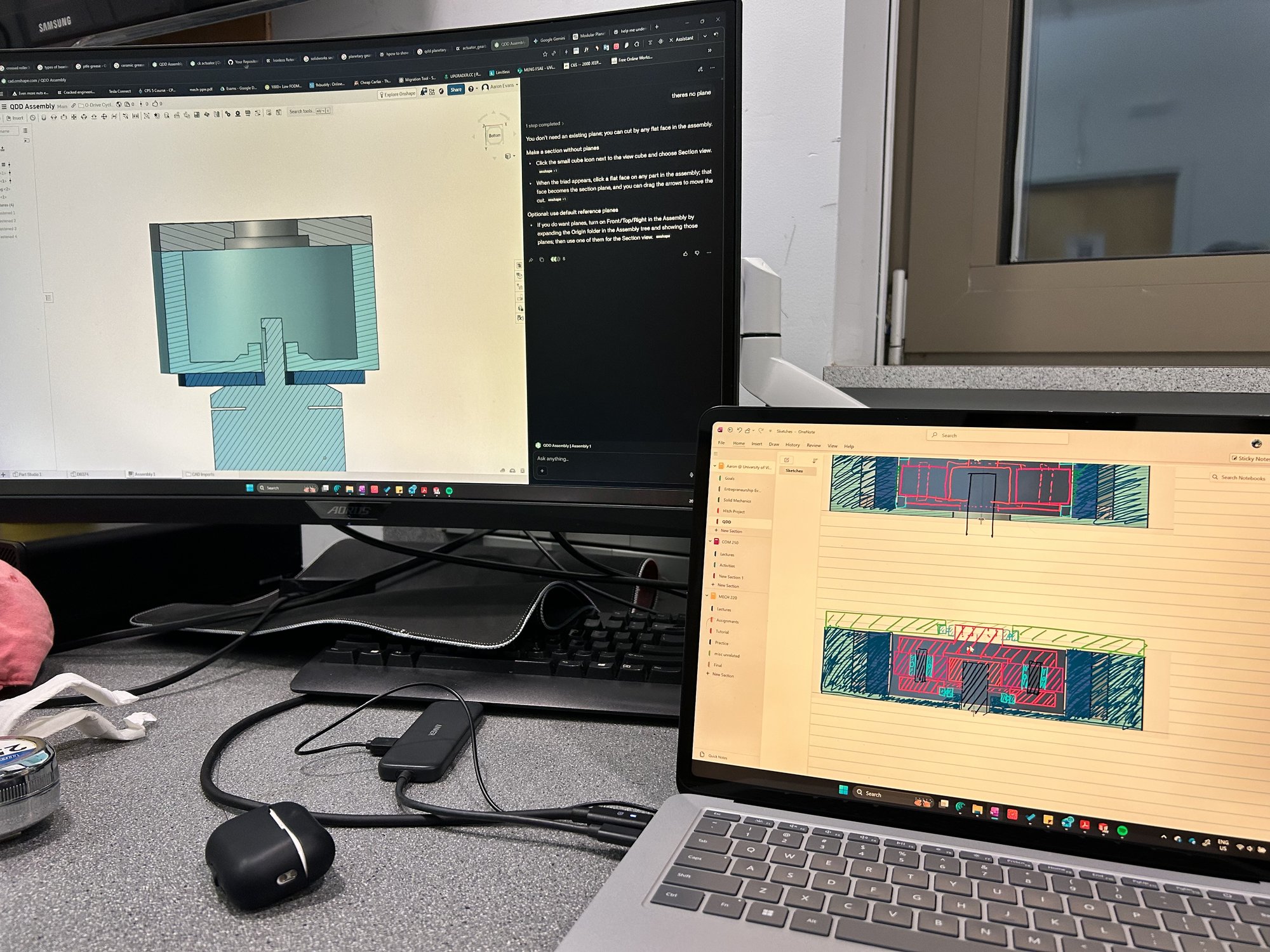
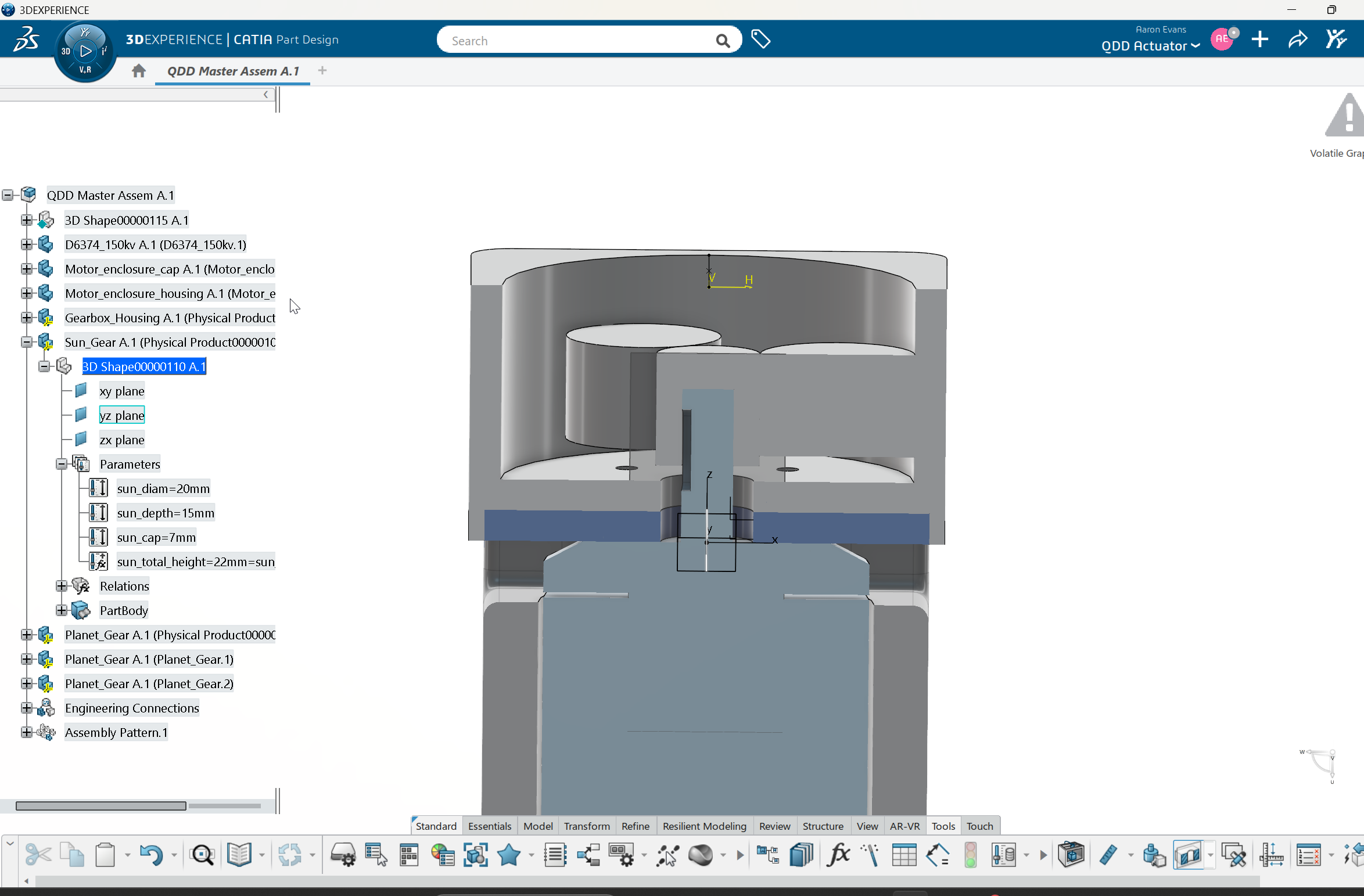
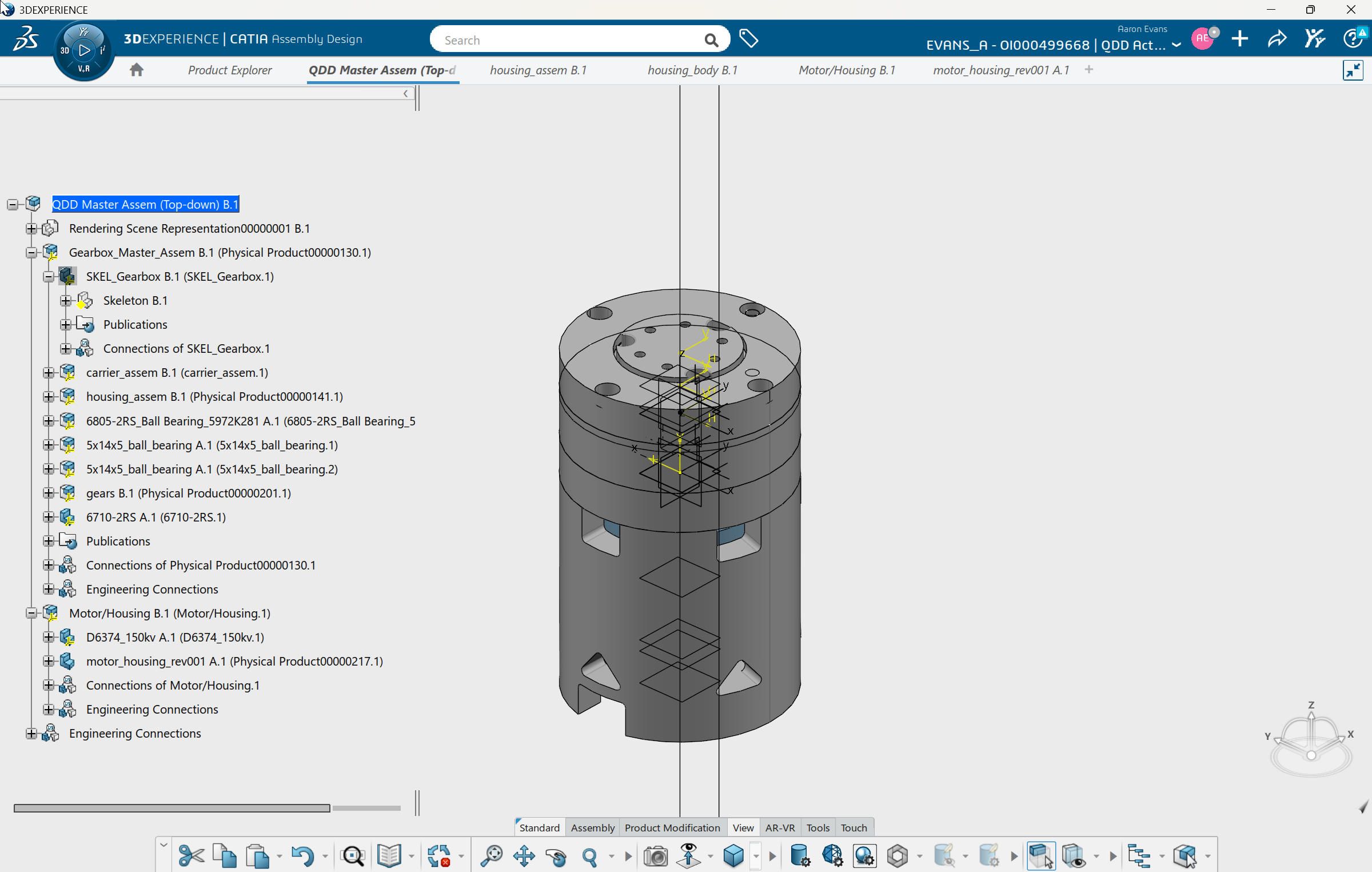
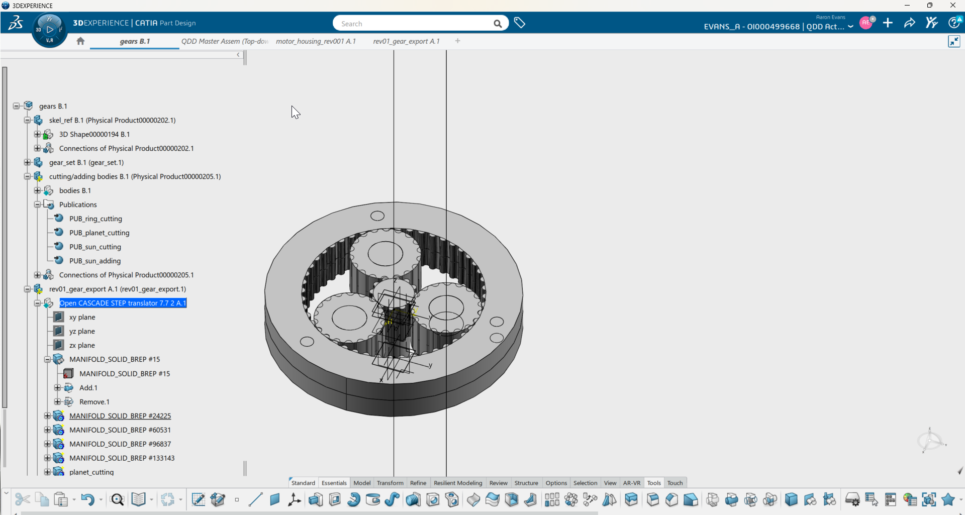
CATIA V6
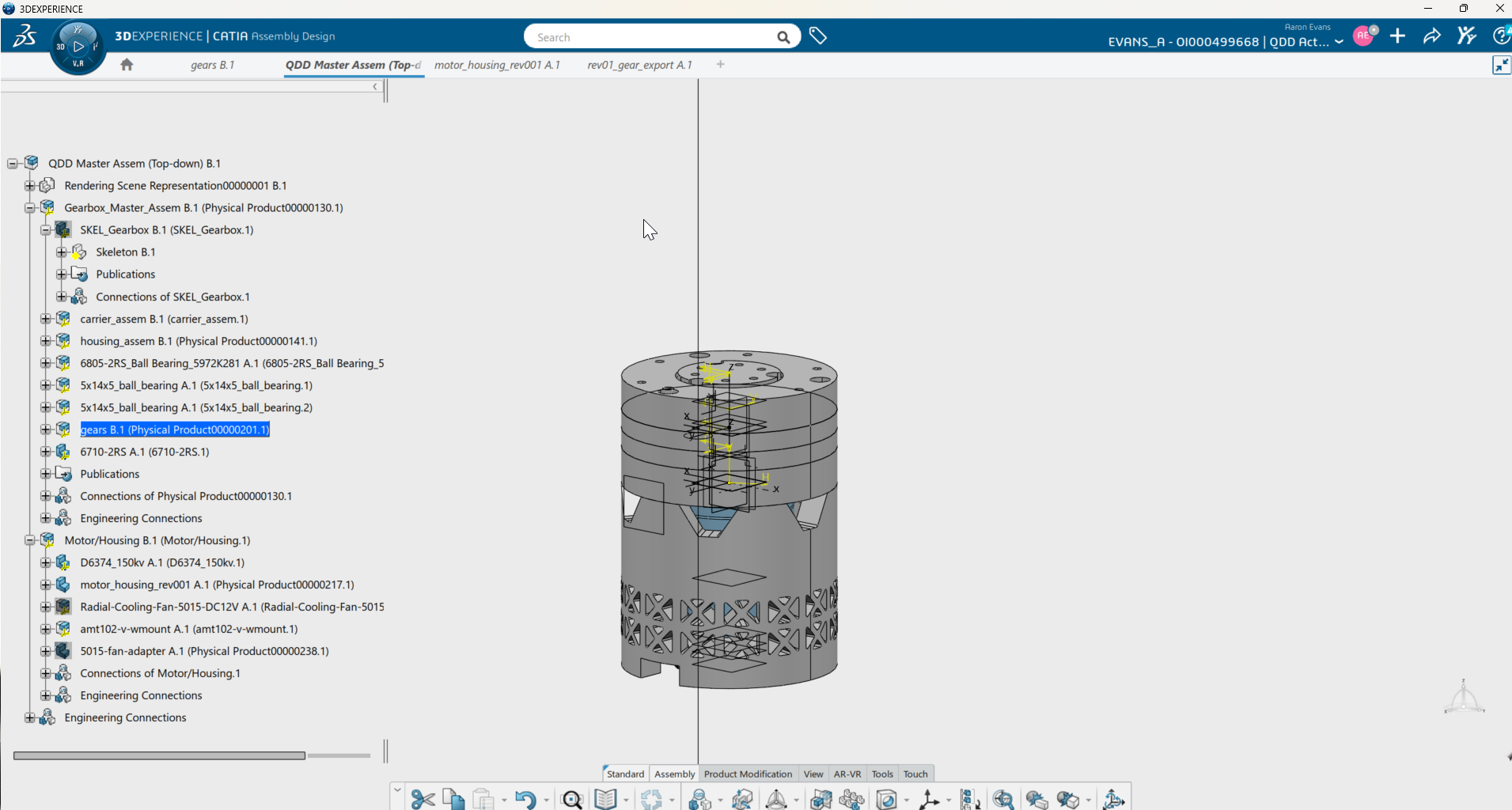
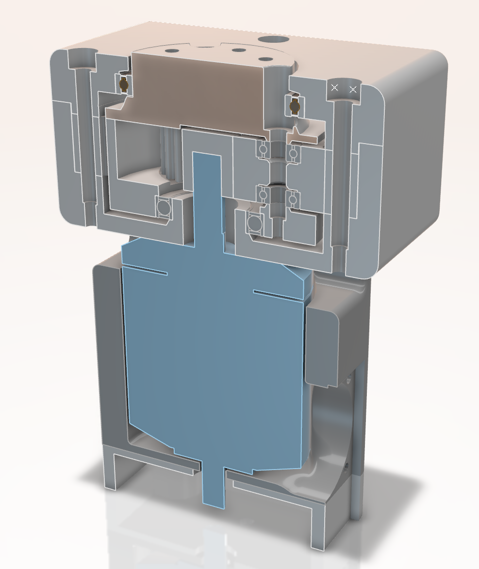
The first concept pass happened in Onshape during the original hackathon day. I rebuilt the project in CATIA because I wanted to learn the CAD software used in a lot of industry work. About 60-80 hours of self-directed learning went into that assembly, much of it in rebuilding the model so future parameter changes would not break downstream parts.
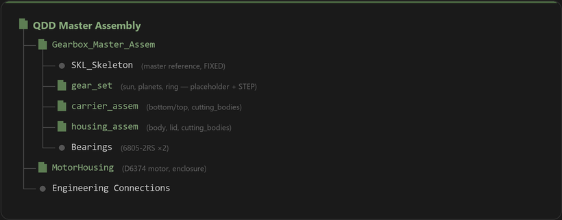
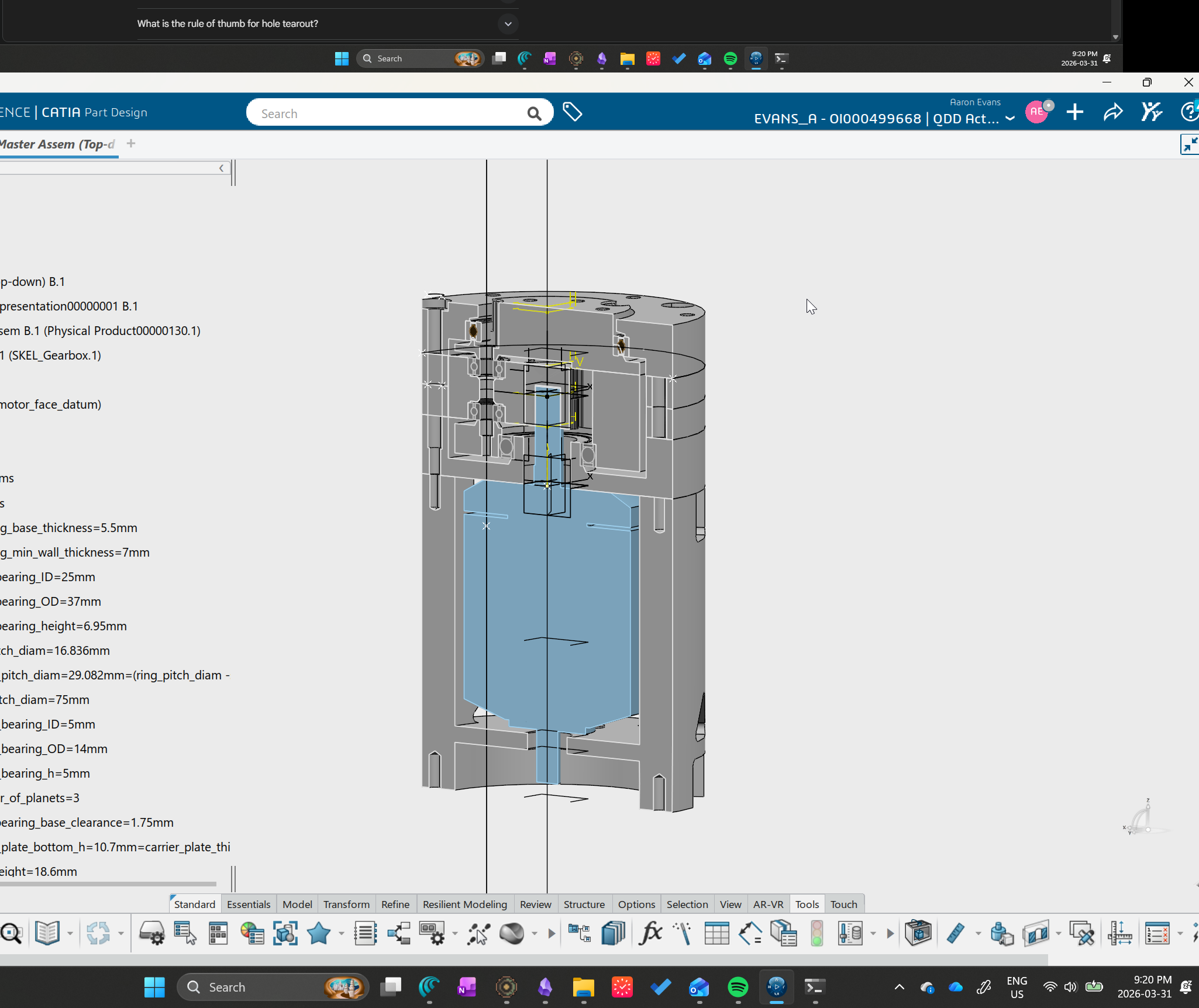
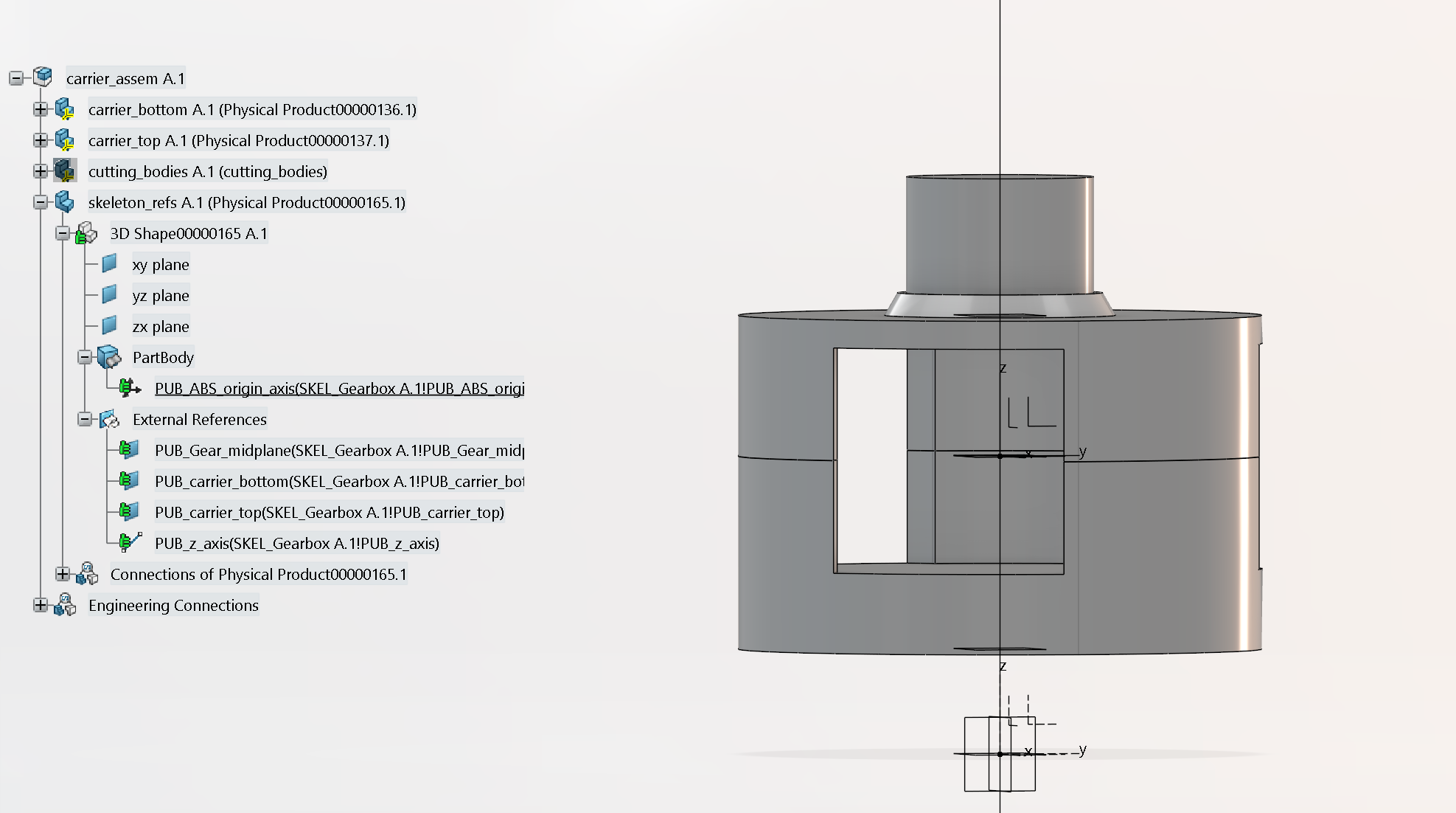
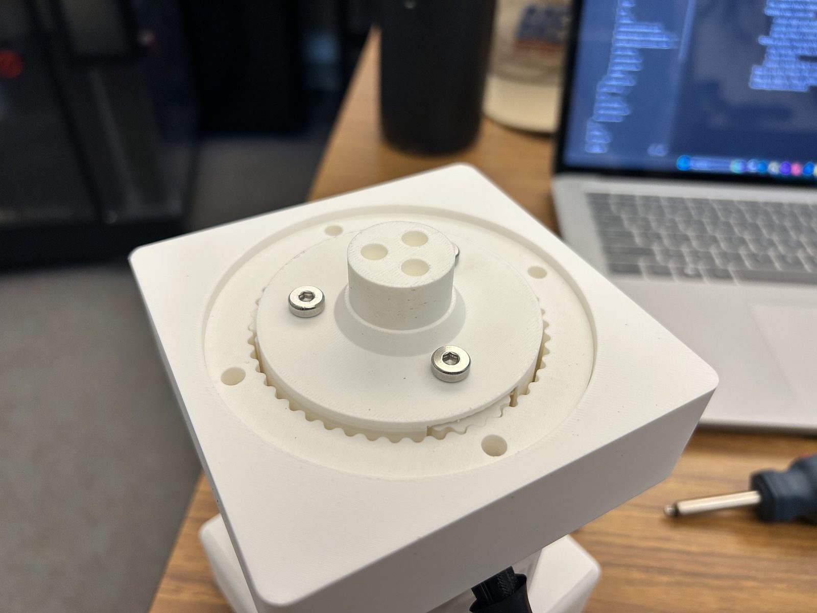
The assembly is skeleton-driven: one master part holds the main parameters, reference planes, and axes. The rest of the parts reference that skeleton, so when I change a key dimension the related parts update with it.
FDM Tolerancing
FDM prints aren't accurate enough for bearing fits out of the box. Bores print undersized by 0.1-0.4mm depending on diameter, so every bearing interface needs a calibrated offset in the CAD model. I keep each offset as a named parameter in the CATIA skeleton, which means the nominal bearing dimensions stay clean and I can tune each fit independently.
All bearing interfaces target a firm finger-press transition fit. For this prototype, that was enough for retention without pushing the fits tighter than needed.
| Interface | Offset | Status |
|---|---|---|
| Housing bearing shaft | +0.10 mm | Validated |
| Carrier bearing bore | +0.10 mm | Validated |
| Lid bearing bore | +0.10 mm | Validated |
| Carrier output shaft | +0.10 mm | Applied |
| Planet bearing bore | +0.15 mm | Validated |
| Ring-to-housing bore | +0.30 mm | Validated |
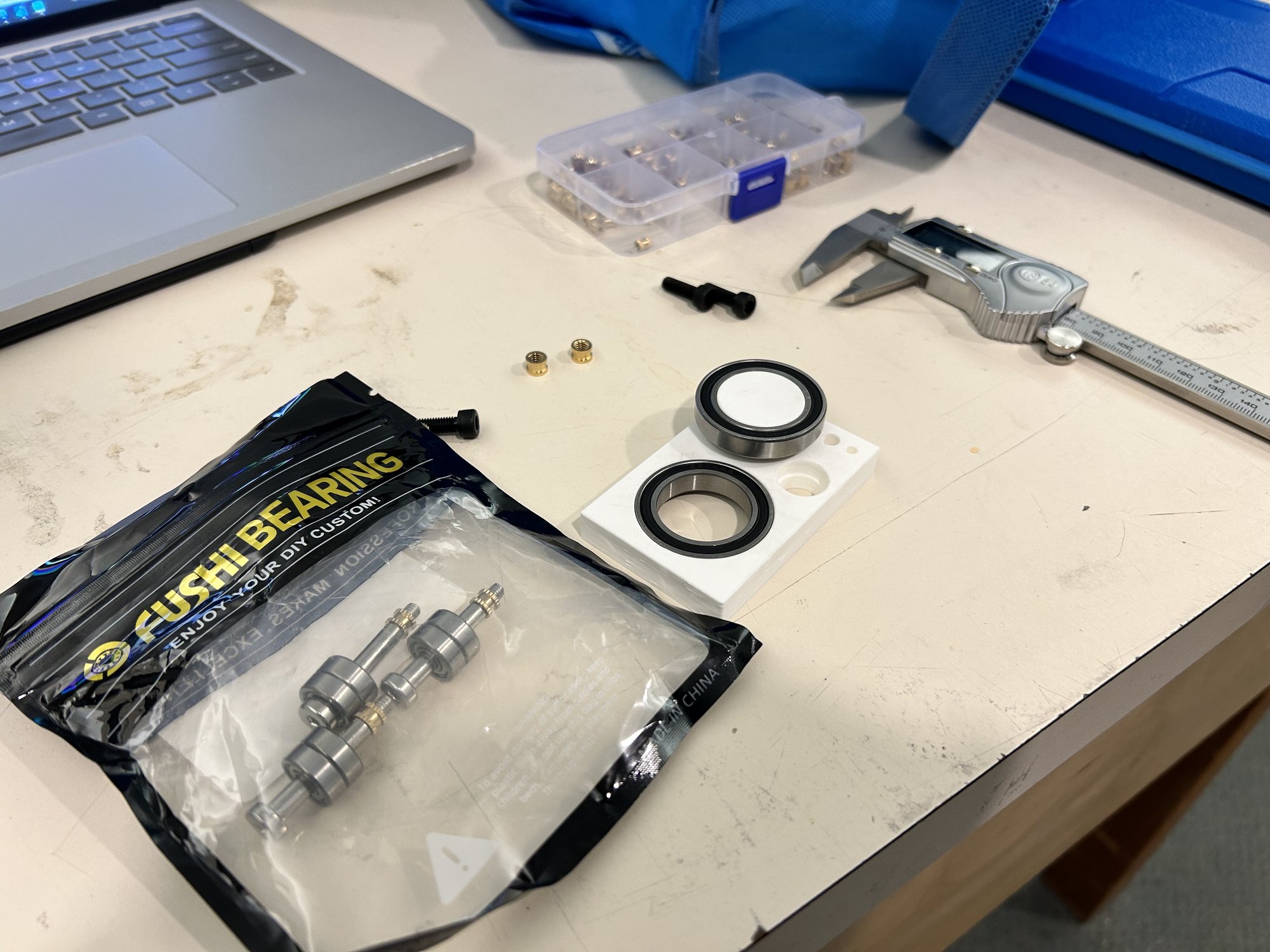
Calibration Coupon
Before printing the full build, I printed a test coupon with representative features (bearing bores, shaft posts, clearance holes) and measured each one with calipers. The results went straight back into the CATIA offsets.
| Feature | Nominal | Measured | Deviation | Result |
|---|---|---|---|---|
| Main bearing bore | 37.10 mm | 37.10 mm | 0.00 | Perfect fit |
| Bearing shaft post | 25.10 mm | 25.01 mm | -0.09 | Good |
| Planet bore | 14.00 mm | 13.75 mm | -0.25 | Offset increased |
| M3 clearance holes | 3.40 mm | ~3.00 mm | -0.40 | Offset extrapolated |
Smaller holes had worse deviation, which makes sense given FDM accuracy scales with feature size. The planet bore and clearance holes needed the largest corrections. I also ended up switching from heat-set inserts to self-tapping screws (M3: 2.6mm pilot, M4: 3.6mm, M5: 4.6mm), which was simpler and worked well for this prototype.
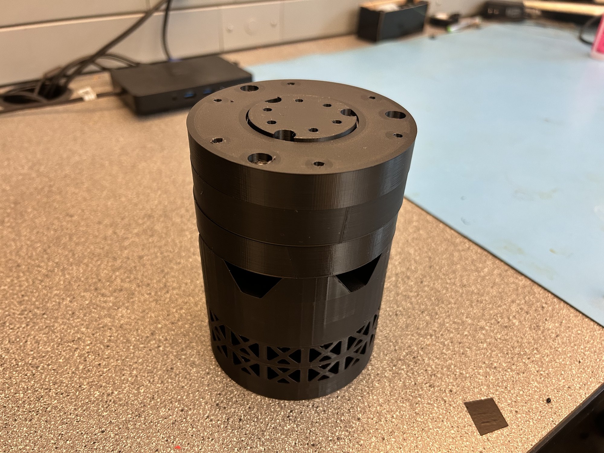
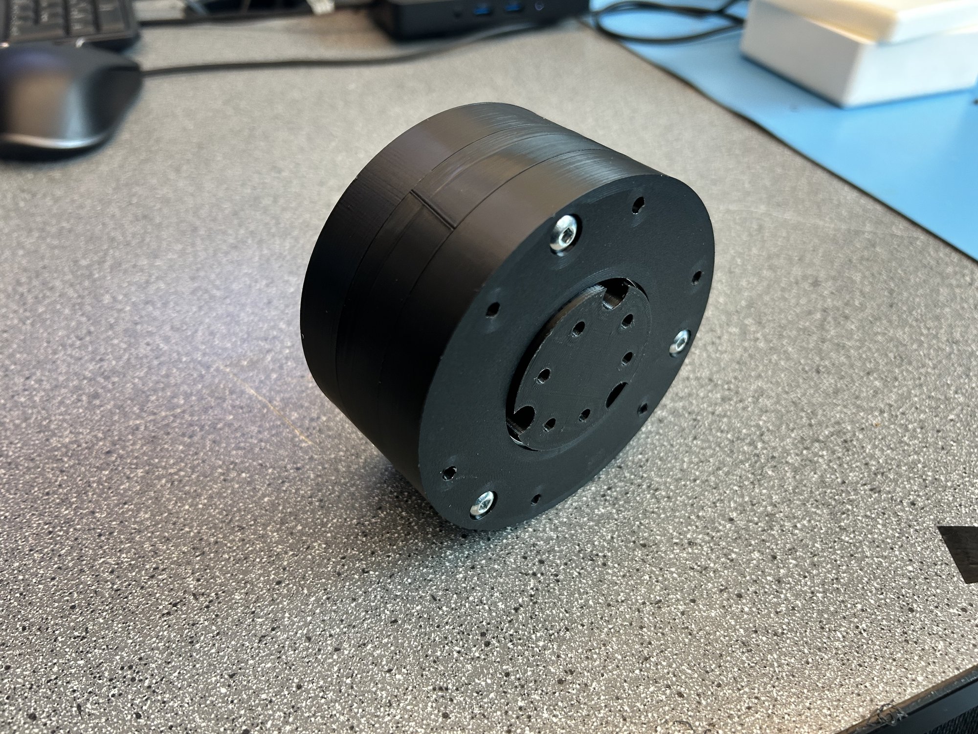
Prototyping
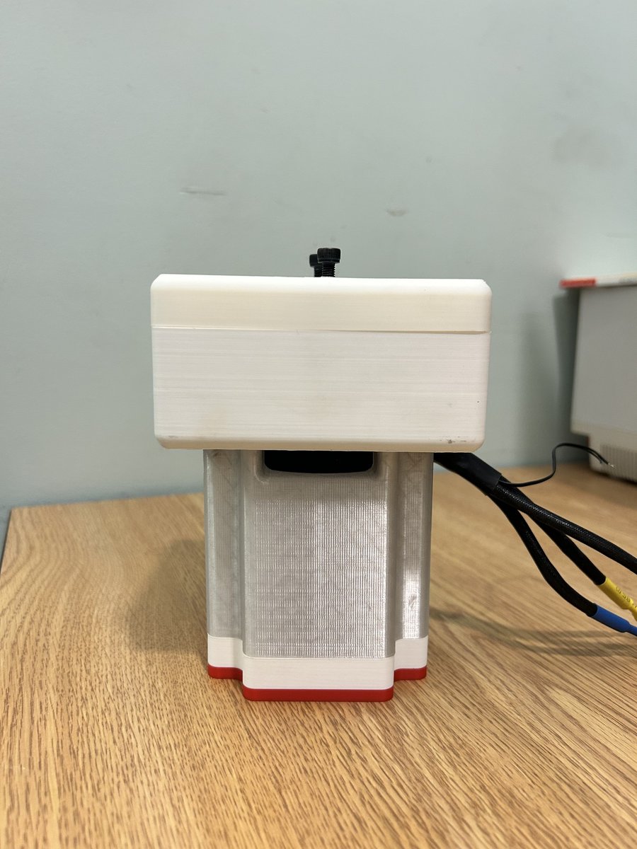
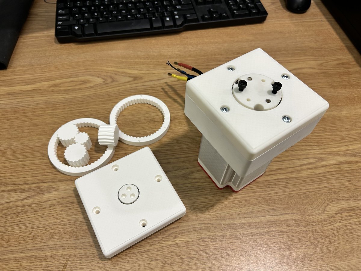
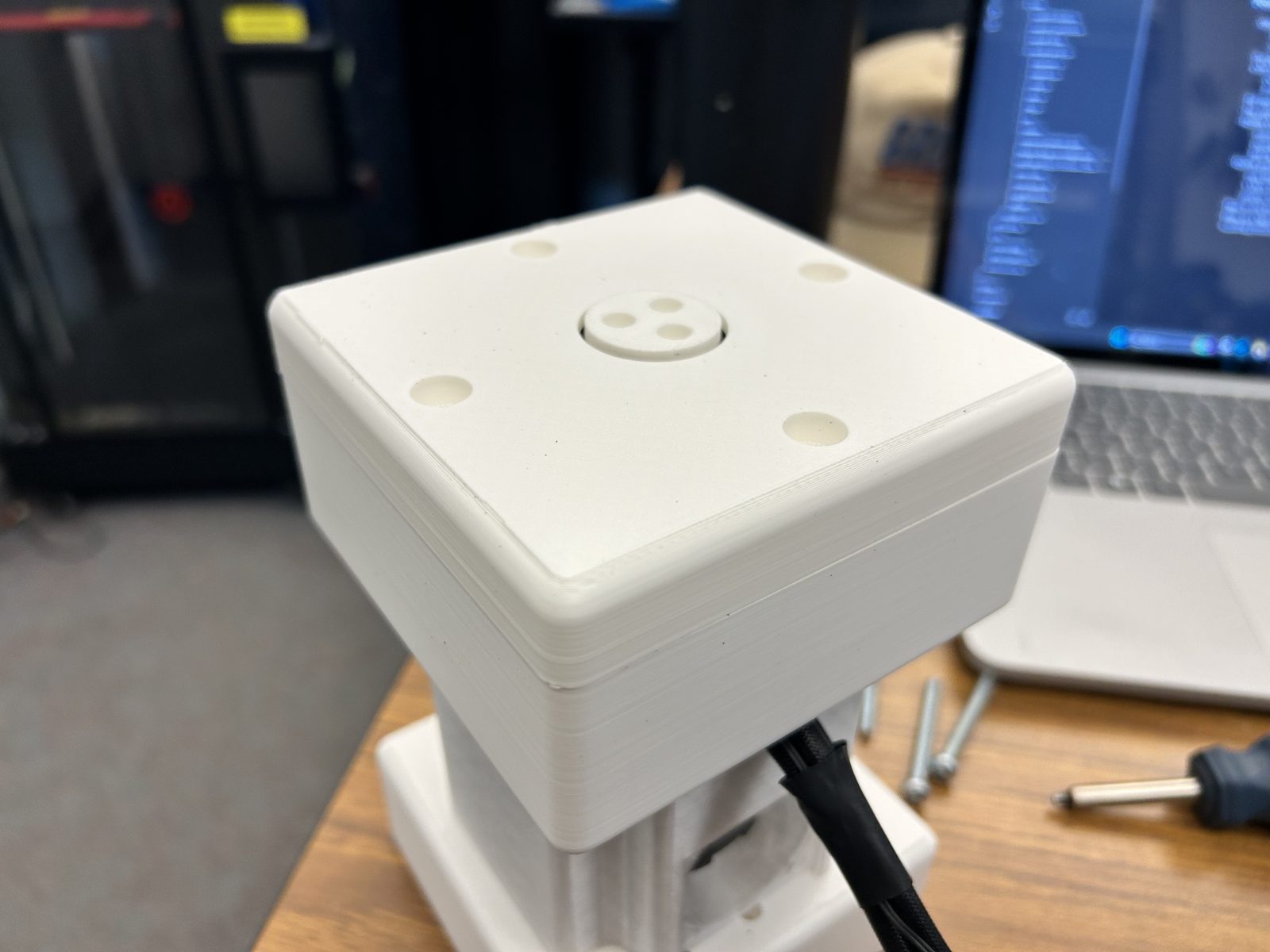
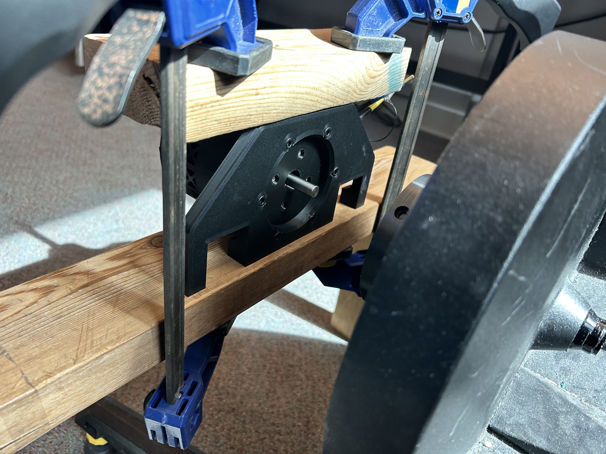
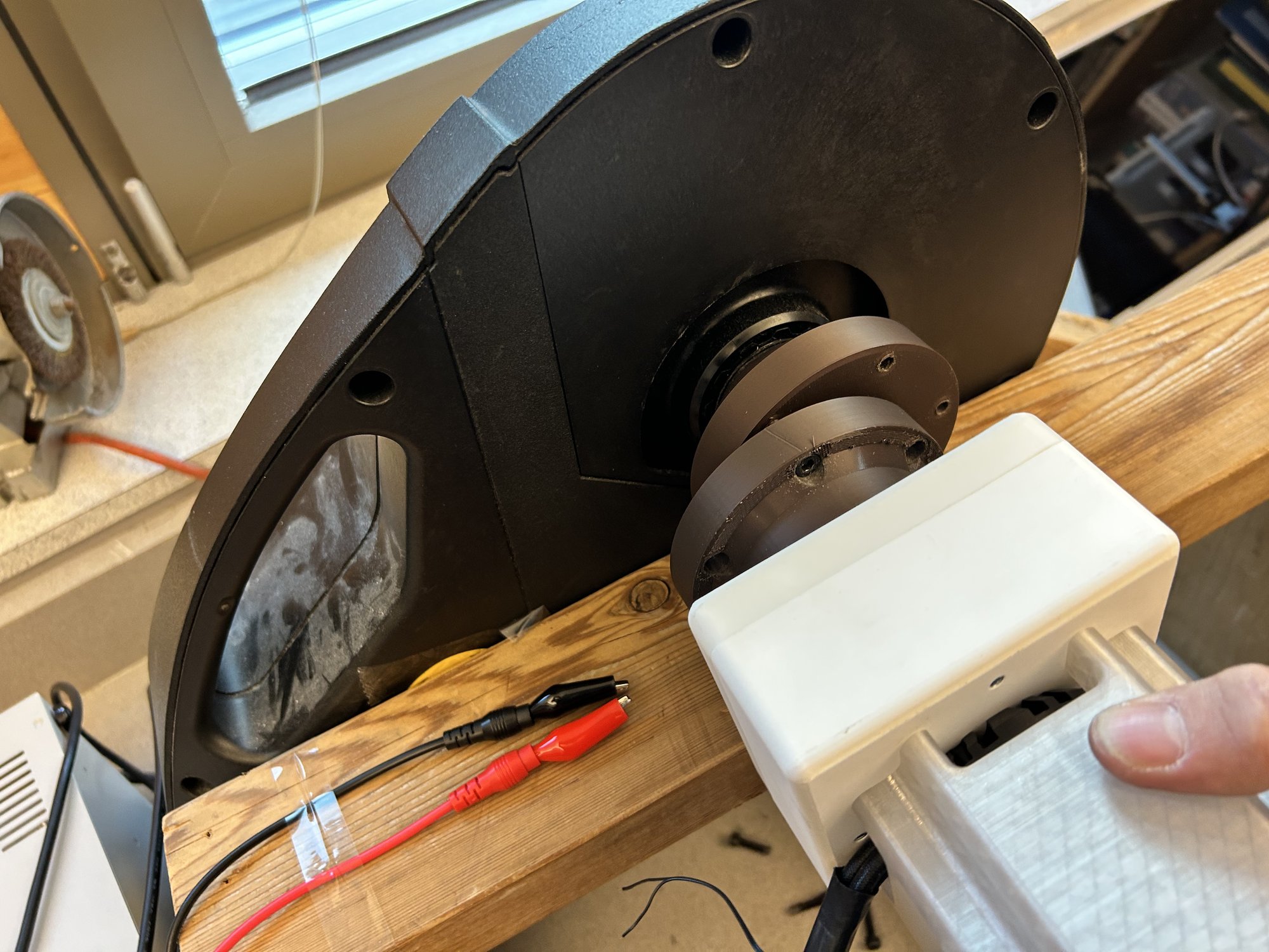
Rev 01 is the current assembled build. The main change is the integrated motor housing and the hardware for the dyno setup.

Testing
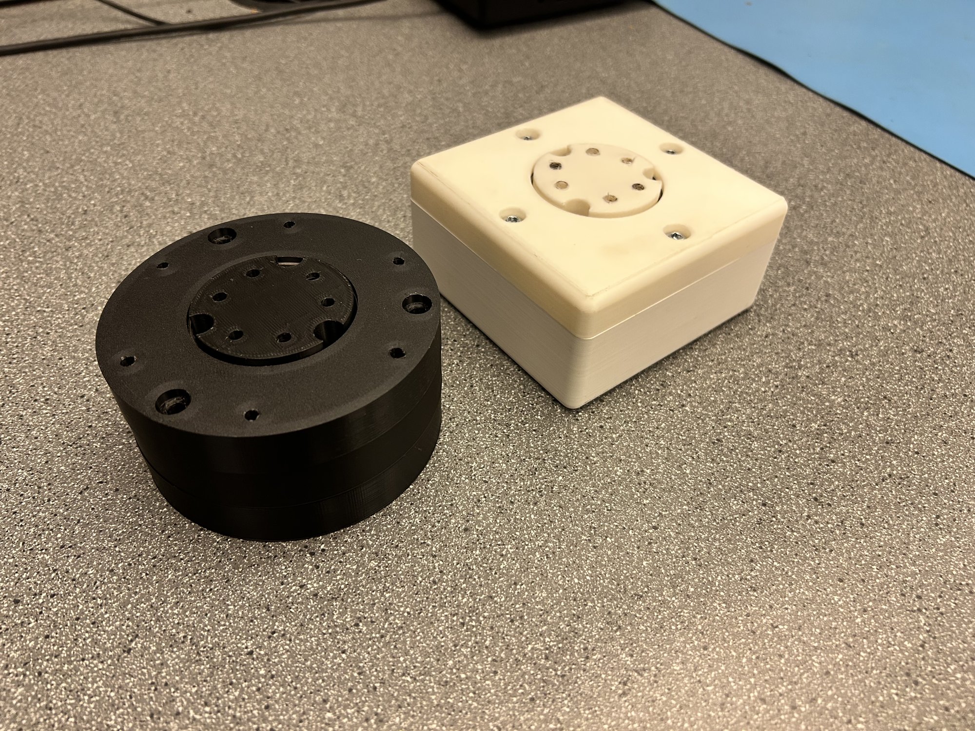
Fixture Evolution
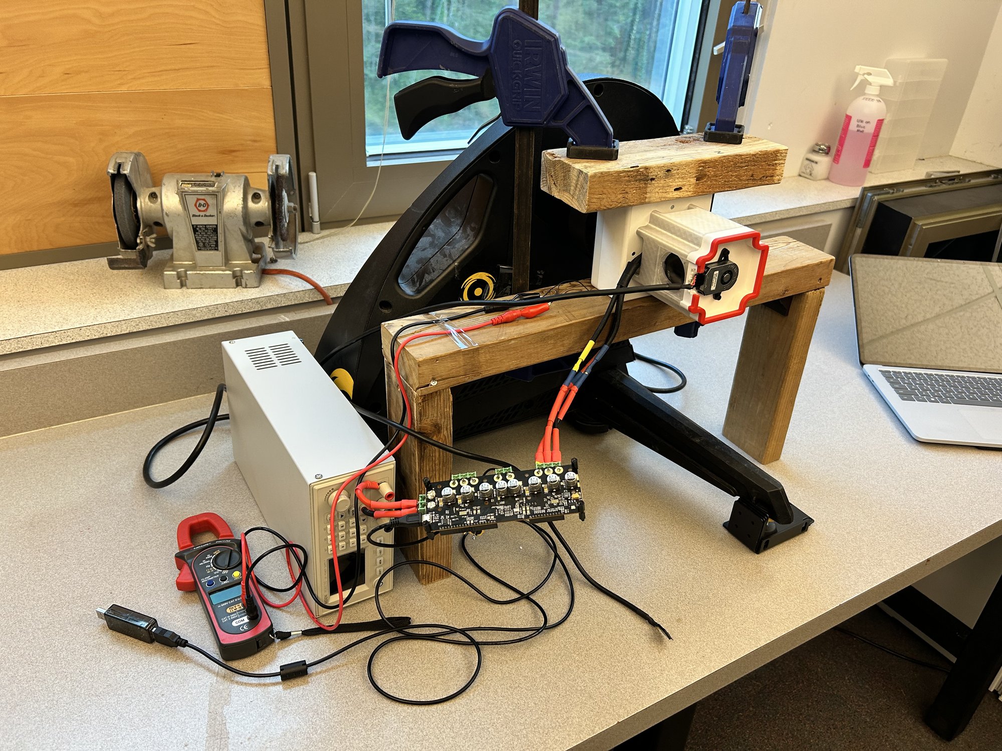
Rev 01 shifted the setup toward a more repeatable dyno fixture. We started by mounting the motor on its own so Russell could get the H2 trainer and motor controllers set up before coupling the gearbox back in. That fixturing is now figured out. The remaining work is running the motor and gearbox together against the remaining requirements.
Requirement Verification
With Rev 00B assembled and the fit issues resolved, I started checking the gearbox against the project requirements.
| Test | Requirement | Result | Status |
|---|---|---|---|
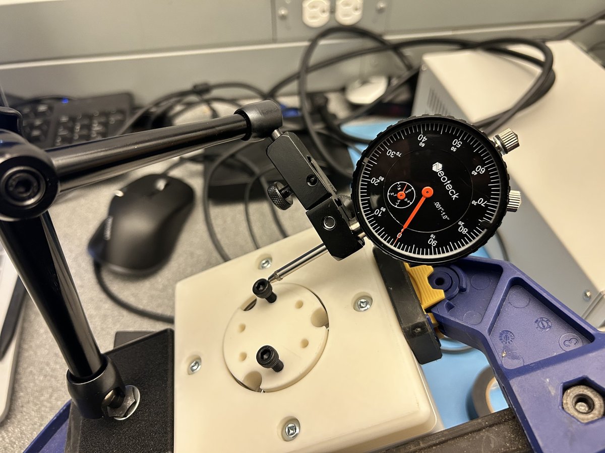
| T-012 Backlash | ≤ 0.5° | 0° | PASS |
| T-013 Backdrivability | < 1 Nm | — | In progress |
| T-020 Peak Torque | ≥ 16 Nm | — | Pending |
| T-021 Continuous Torque | ≥ 12 Nm | — | Pending |
| T-022 Efficiency | > 90% | — | Pending |
| T-023 Speed Endurance | ≥ 600 RPM | — | Pending |
| T-024 Health Comparison | No major damage | — | Pending |
What's Next
Rev 01 is assembled and installed in the motor housing. The remaining work is test execution. Backdrive torque is next, using a lever arm and kitchen scale to measure friction against the 1 Nm requirement. After that, the remaining checks are peak torque, continuous torque, efficiency, speed endurance, and the post-test health comparison. Geometry and fixturing are settled, so the project has shifted from build changes to finishing the requirement test sweep.